
Method for controlling a safety system in a vehicle

a safety system and vehicle technology, applied in the direction of pedestrian/occupant safety arrangement, tractors, instruments, etc., can solve the problems of insufficient speed or course of well-known methods, high insufficient protection for occupants, and significant limitation of maximum attainable protection effect, etc., to achieve rapid and reliable recognition of accidents, reduce the risk of accidents, and reduce the effect of accidents

Active Publication Date: 2007-01-02
BAYERISCHE MOTOREN WERKE AG
View PDF14 Cites 17 Cited by
  • Summary
  • Abstract
  • Description
  • Claims
  • Application Information

AI Technical Summary

Benefits of technology

[0006]It is therefore an object of the present invention to create a method with improved reliability for controlling a safety system in a vehicle that is effective for pedestrians and / or bicyclists.
[0008]The current velocity of the vehicle v and the outside temperature of the vehicle θ are given a special value. In both cases this involves easily measurable parameters, which are also conventionally recorded for other electronic control units in the vehicle. Vehicle velocity v is taken into account in the method of the present invention because there is a surprising influence on the sensor signal spectrum when there is a hard on soft and a soft on soft impact. It has also become known that the elements of a vehicle become less elastic as the outside temperature θ of the vehicle drops, so that a material that is soft under normal conditions reacts like a progressively harder material as the temperature drops. This is especially true for a soft outside bumper covering that is relatively soft under normal conditions. Taking at least one of these parameters into account therefore clearly increases the detection reliability of a method according to the present invention.
[0010]The materials mentioned above have in common that they can be used as passive sensors, with self-testing also being possible in a simple manner by making use of the reciprocity of piezo-electric materials with external active control and subsequent evaluation by a central system unit. For this purpose, the sensor element is therefore first controlled as an actuator, with the mechanical oscillation thus excited again being sensed as an electrical signal if the element is working without interference. This sensing can be performed by the sensor operated exactly as an actuator just as by at least one adjacently arranged sensor. This makes it possible for each sensor of a sensor field to be checked and monitored at any time for its operating properties with no additional expense for equipment like signal transmitters, etc.
[0011]In addition to the self-test of a particular sensor, however, a mechanical oscillation can also be imposed on a system to be safeguarded or monitored by the actuator operation, with an analysis of the oscillation created being subsequently provided by the same element with the properties of this system response being examined in an evaluation unit of the actual safety system. In addition to deformations of the material, cracks and other disturbances can also be detected in this way, especially by a frequency pattern that deviates from this system response. Thus, the present invention provides a method for operating a sensor with a reciprocal mechanism of action in a safety system, and offers the advantages of reliable self-testing. The present invention also provides the advantage of safety testing and system analysis provided at minor expense and with negligible interference in an overall mechanical system to be monitored, and with a diagnosis to complete each test. Prior damage of certain parts inside a motor vehicle can thereby be detected at any time and can be taken into account as well during the analysis of a possibly currently occurring accident, since each type of prior damage causes either a softening of parts of the frame or stiffening but in each case a deviation from unimpaired normal behavior.
[0014]In the event that non-harmonic oscillations develop, as, for example, in the case of impact with a foreign object or a pedestrian, precise identification of a particular event and location of its position are possible via the particular sensor elements. Accordingly, an evaluation of the intensity of the particular output signals is performed, which can be linked with a measurement of signal-transit time. Taken together, these rapidly give a reliable picture of an impact with a conclusion about the location or locations of the impact and the type of object or human being with which there has been an impact.
[0016]A method according to the invention is therefore also distinguished in its developments in that the use of robust, overload-resistant, cost-effective sensors that can be safely used over a wide temperature range and are capable of self-diagnosis, allows rapid and very reliable recognition of accidents with a pedestrian or bicyclist.

Problems solved by technology

This is highly inadequate protection for the occupant(s) due to both too early and too late an activation of the appropriate airbags, seat belt tensioners and / or anti-rollover devices, etc.
Methods which also offer the possibility of protecting pedestrians and / or bicyclists as early warning systems can be constructed on the basis of the methods and devices described above with only a very significantly limited maximum attainable protective effect.
Even this well-known method is not rapid enough with respect to the progress or course of an impact acting on the vehicle involved, and can have substantial weaknesses in terms of its robustness where the vehicle is coated with dirt, ice or snow and / or is hit by road debris.
This kind of animal therefore hits the windshield usually with no brakes being applied and very often breaks through it due to its own body weight.
This poses extreme danger to the driver and any passenger so that active protective measures must be adopted here for occupants as well.

Method used


Image

  • Method for controlling a safety system in a vehicle
  • Method for controlling a safety system in a vehicle
  • Method for controlling a safety system in a vehicle

Examples


Embodiment Construction

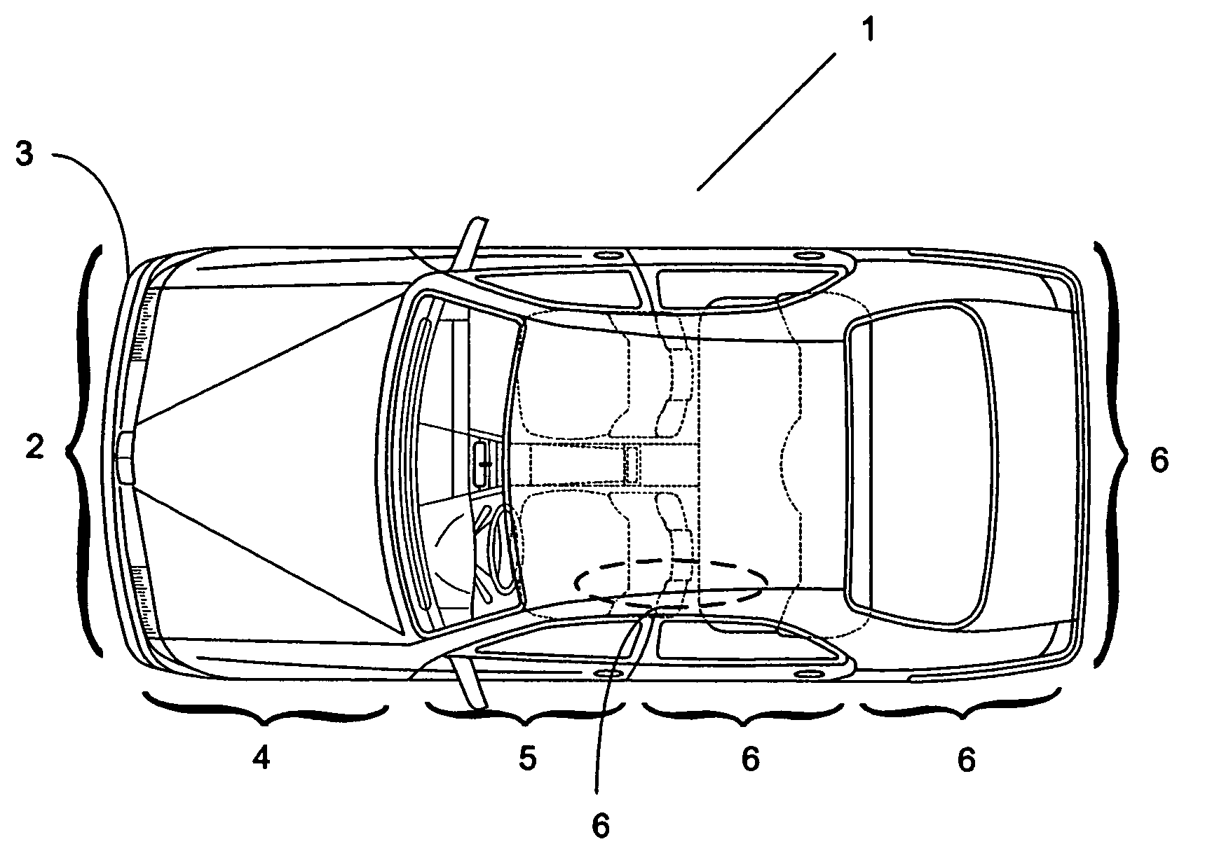
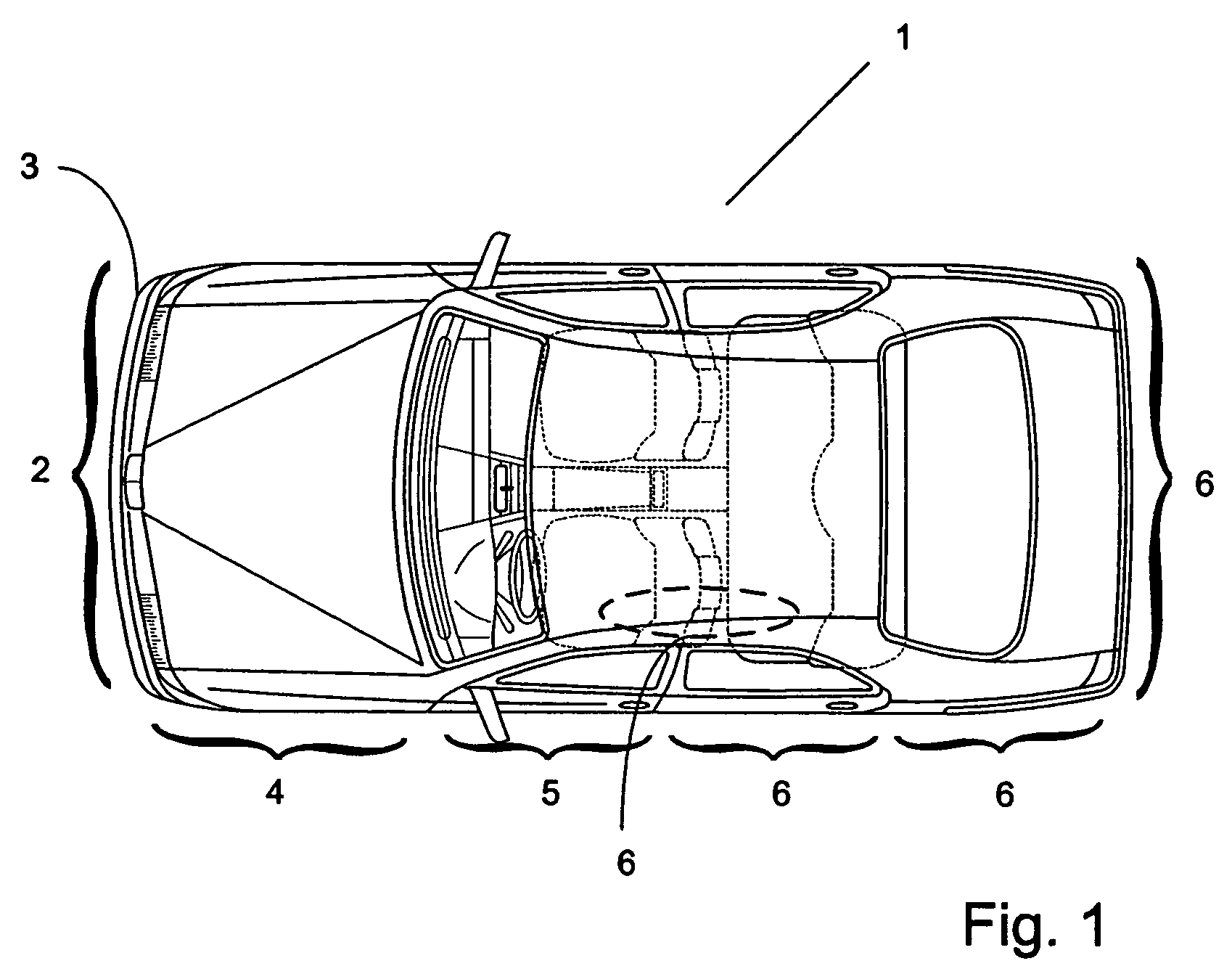
[0022]FIG. 1 shows a diagram of a motor vehicle 1 which is equipped with sensors 2 (not shown here in detail) of a safety system according to the present invention in a bumper or fender 3. In accidents involving a pedestrian or bicyclist, fender 3 is usually the point at which the initial impact takes place. In a side impact, this initial contact can also take place at a left or right fender 4 or a driver's or passenger's door 5. Further areas of use 6 for sensors 2 of a safety system according to the present invention have been indicated by curved brackets in the top view for half of motor vehicle 1.

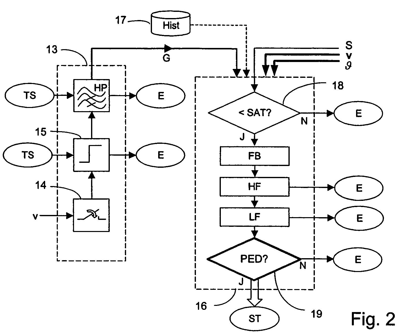
[0023]FIG. 2 shows a flow chart of an embodiment into which the method of the present invention can be integrated. An initial block 13 represents the processing of a triggering signal TS which comes from the sensor 2 that first becomes sufficiently deformed due to an impact. This is also called the trigger sensor signal. The prerequisite for processing triggering signal TS is, however, ...


PUM


Abstract

In a method for controlling a safety system in a vehicle, wherein an output signal of at least one impact sensor is subjected to frequency analysis in an evaluation unit which is integrated into an electronic control unit, the frequency analysis is performed in at least one predetermined frequency range, the spectrum of the output signal is compared with references patterns, the dependence of the spectrum on the present speed of the vehicle and / or the present outside temperature of the vehicle is taken into account, and a triggering signal is generated from the control unit to trigger planned protective measures if a person to be protected is detected with at least a predetermined probability.

Description

BACKGROUND AND SUMMARY OF THE INVENTION[0001]The present invention is related to a method for controlling a safety system in a vehicle and a control device.[0002]Numerous methods and devices for controlling a safety system are known which are predominantly aimed only at the protection of the occupants of a motor vehicle using at least one impact sensor. Accordingly, an accident analysis is also usually conducted only from the standpoint of the timely activation of known occupant-protection equipment with the goal of effective absorbing the impact on occupants resulting from a change in vehicle speed due to an impact or an accident. Therefore, triggering strategies are regularly selected and implemented in the prior art on the basis of measured and / or calculated acceleration vectors in order to avoid, by the purposeful choice of occupant-protection equipment with a specifically directed effect. This is highly inadequate protection for the occupant(s) due to both too early and too lat...

Claims


Application Information

Patent Timeline
Patent Type & Authority Patents(United States)
IPC IPC(8): B60Q1/00B60D1/28B60R21/16B60R22/00
CPCB60R21/013B60R2021/01184B60R2021/01068
Inventor BAUR, RICHARDLU, YANNEUBERGER, RALPH
Owner BAYERISCHE MOTOREN WERKE AG
Learn More