Eureka AIR delivers breakthrough ideas for toughest innovation challenges, trusted by R&D personnel around the world.

Heat exchanger with thermal inertia for a heat transfer fluid circuit, particularly of a motor vehicle

a heat exchanger and fluid circuit technology, applied in the field of heat exchangers, can solve the problems of increasing cramped space dedicated to the various equipment items, particularly in the engine compartment, and discomfort of passengers or passengers of the vehicl

Active Publication Date: 2007-01-02
VALEO CLIMATISATION SA
View PDF19 Cites 65 Cited by
  • Summary
  • Abstract
  • Description
  • Claims
  • Application Information

AI Technical Summary

Benefits of technology

[0015]The invention is particularly beneficial where the heat exchanger is an air-conditioning evaporator. Thus, when the evaporator is operating, that is to say when the cooling fluid circulates under the action of the compressor, the evaporator produces cold. That makes it possible both to cool the flow of air that is to be sent into the cabin of the vehicle and also to solidify the phase-change fluid or keep it in this solidified state.
[0017]This then affords an evaporator with significant thermal inertia making it possible to cool the air flow even when the vehicle engine is stopped for periods which may reach and exceed, for example, thirty seconds.
[0018]The invention is also particularly beneficial where the heat exchanger is a heating radiator. This is because when the radiator is in operation and the heating fluid is circulating under the action of heat, the radiator produces heat. That makes it possible both to heat up the flow of air that is to be sent into the cabin, and also to store heat in the heat storage fluid, the temperature of which rises and may possibly experience a phase change.

Problems solved by technology

One of the disadvantages with the known evaporators lies in the fact that their ability to cool the air flow depends on the operation of the compressor.
The stopping of the internal combustion engine causes the stopping of the compressor, hence causing the passenger or passengers of the vehicle to experience discomfort.
These known solutions are bulky and complicated to produce and prove to be somewhat incompatible with modern vehicles in which the space dedicated to the various equipment items, particularly in the engine compartment, is becoming increasingly cramped.
A similar problem may arise when the heat exchanger is produced in the form of a heating radiator through which a heating fluid runs, because this fluid is set in motion by a pump, also known as the “water pump”, which is conventionally driven by the vehicle's internal combustion engine.
Thus, when the engine is stopped, this stops the pump and therefore stops the circulation of the fluid, hence giving rise to an experience of discomfort, especially when the exterior temperature is very low.

Method used


Image

  • Heat exchanger with thermal inertia for a heat transfer fluid circuit, particularly of a motor vehicle
  • Heat exchanger with thermal inertia for a heat transfer fluid circuit, particularly of a motor vehicle
  • Heat exchanger with thermal inertia for a heat transfer fluid circuit, particularly of a motor vehicle

Examples


Embodiment Construction

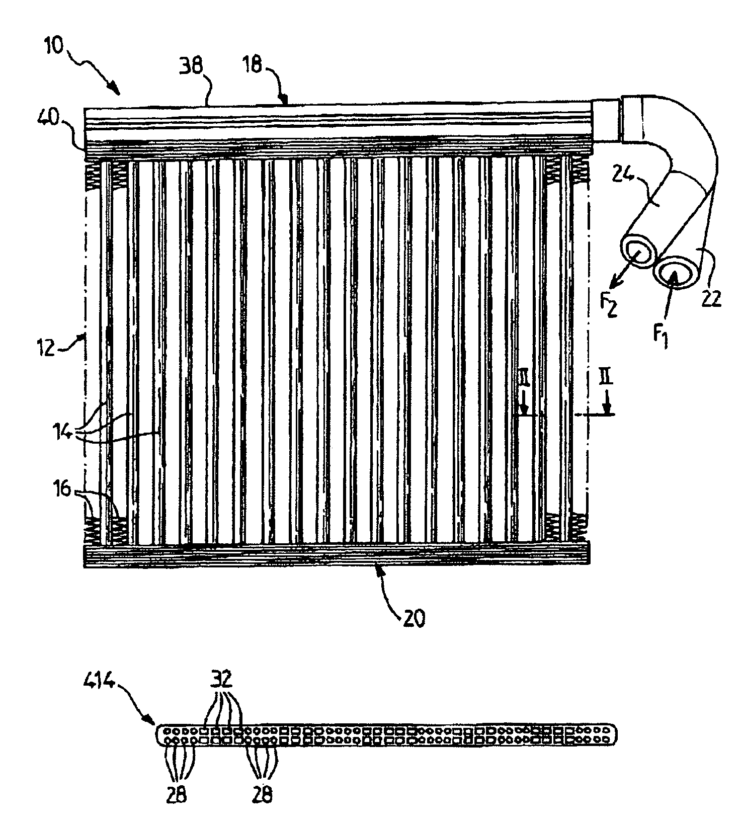
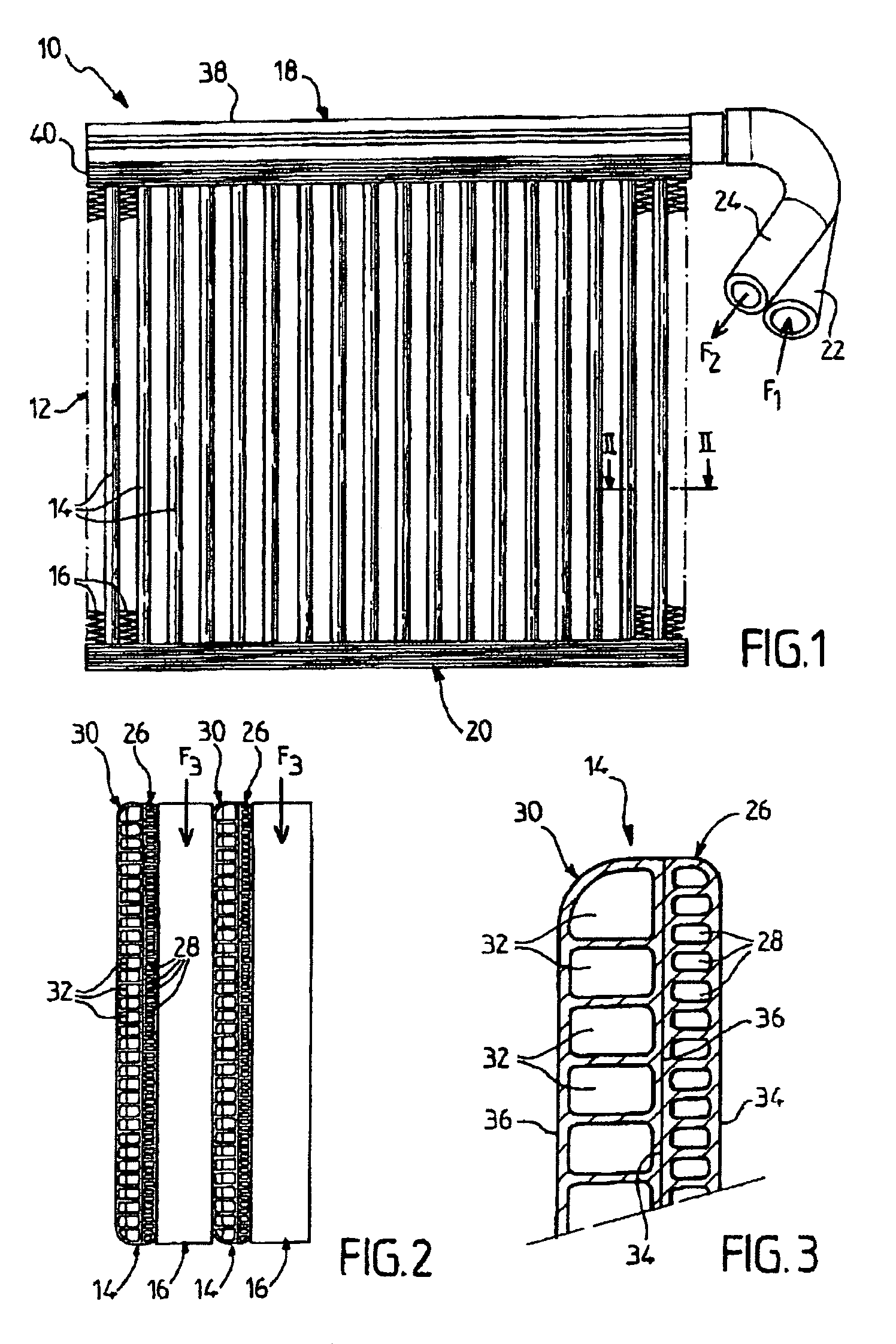
[0044]In the detailed description which follows, reference is made to the particular case of an evaporator, but the characteristics thereof apply also to a heating radiator, as mentioned hereinabove. Reference will first of all be made to FIG. 1 which shows an evaporator 10 able to form part of a conventional air-conditioning circuit (not depicted) of a motor vehicle, in which a cooling fluid passes in succession through a compressor, a condenser and an expander before reaching the evaporator then returning to the compressor.

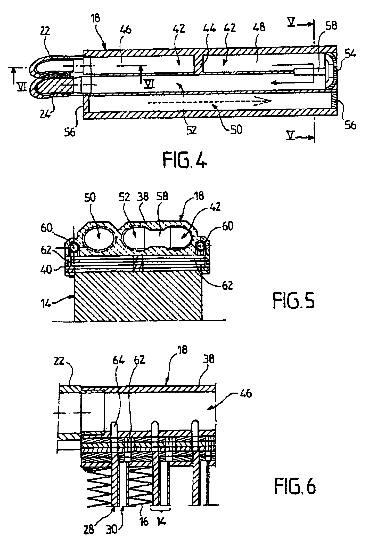
[0045]The evaporator 10 comprises a body or bundle 12 formed of a multiplicity of parallel tubes 14 which alternate with corrugated inserts 16 forming heat-exchange surfaces. The bundle 12 is inserted between two manifolds, namely a manifold 18 here placed at the upper part and a manifold 20 here placed at the lower part. The manifold 18 is equipped with an inlet nozzle 22 for the cooling fluid in liquid phase or in liquid / vapor phase and with an outlet nozzle 2...


PUM


Abstract

A heat exchanger for a heat transfer fluid circuit comprising ducts for the circulation of the heat transfer fluid, which are inserted between an inlet and an outlet, is described. Cavities designed to contain a heat storage fluid adjacent to the cooling fluid circulation ducts and associated with heat-exchanger surfaces, so that heat storage fluid is capable of exchanging heat with the air flow, if the circulation of the heat transfer fluid is stopped, are also described.

Description

FIELD OF THE INVENTION[0001]The invention relates to the field of heat exchangers, particularly for motor vehicles.[0002]It relates more specifically to a heat exchanger for a fluid circuit through which a heat transfer fluid runs, comprising at least one manifold delimiting an inlet and an outlet for the heat transfer fluid, circulation ducts for the heat transfer fluid which are inserted between the inlet and the outlet, and heat-exchange surfaces associated with the heat transfer fluid circulation ducts and able to be swept by a flow of air that is to be conditioned.[0003]In the particular case of a motor vehicle, the heat exchanger may be produced, for example, in the form of an air-conditioning evaporator through which a cooling fluid runs so as to cool the flow of air and produce conditioned air which is sent into the cabin of the vehicle. The heat exchanger may also be produced in the form of a heating radiator, also known as a unit heater, through which a heating fluid, gene...

Claims


Application Information

Patent Timeline
IPC IPC(8): F28D19/00F28F1/04F25D11/02F28F21/08F25B39/02F25D3/00F28D1/047F28D1/053F28D7/00F28D20/00F28D20/02F28F9/02F28F27/02
CPCF28D1/0476F28D1/05391F28D7/0008F28F9/0214F28F9/026F28D20/02F25B39/02F25D3/005Y02E60/145F28D2020/0013F28D2021/0085Y02E60/14
Inventor HALLER, REGINELEPETIT, LOICPETIT, CHRISTIANLOUP, DIDIER
Owner VALEO CLIMATISATION SA
Why Eureka
Eureka Blog
Learn More