Wide-band fiber-optic tunable filter

a wide-band fiber-optic tunable filter and wide-band technology, applied in the field of fiber-optic filters, can solve the problems of high optical loss, high cost, poor accuracy, need to be further improved, etc., and achieve high extinction ratio, low optic loss, and high sensitivity.

Inactive Publication Date: 2006-12-26
NAT CHIAO TUNG UNIV
View PDF7 Cites 6 Cited by
  • Summary
  • Abstract
  • Description
  • Claims
  • Application Information

AI Technical Summary

Benefits of technology

[0017]According to one aspect of the present invention, a fabricating method of a wide-band fiber-optic tunable filter is provided. In comparison with the traditional fabricating method of the fiber-optic tunable filter, the present invention just adopts normal fibers rather than expensive specialized fibers to fabricate the fiber-optic tunable filters. The fiber-optic tunable filter provided by the present invention is advantageous in a low optic loss, a wide-band tunability, a high extinction ratio, a high sensitivity and a small size. Such a fiber-optic tunable filter is fabricated by positioning optical polymers on the evanescent-field region of a polished fiber. The volume of the packed filter is about equal to the size of a steel cylinder, e.g. the length of 25 mm and the diameter of 2 mm, and the tunable range of the wavelength thereof is at least 400 nm, which is wide enough for covering all the bandwidth for the fiber-optic communication systems. Moreover, the cost of the previous fiber0optic tunable filter is efficiently decreased, and hence the fiber-optic tunable filter of this invention is suitable for the fiber-to-the-home (FTTH) system networks.

Problems solved by technology

However, these methods both need specialized kinds of fibers, which cost much and have high optical losses.
The fiber-optic band-pass filter as well as the fiber-liquid-refractive-index meter fabricated by the mentioned methods, however, both have a poor accuracy and need to be further improved.
However, such schemes are disadvantageous in the high costs because of the adoption of the specialized fibers, and hence the schemes are hard to be popularized.

Method used


Image

  • Wide-band fiber-optic tunable filter
  • Wide-band fiber-optic tunable filter
  • Wide-band fiber-optic tunable filter

Examples


Embodiment Construction

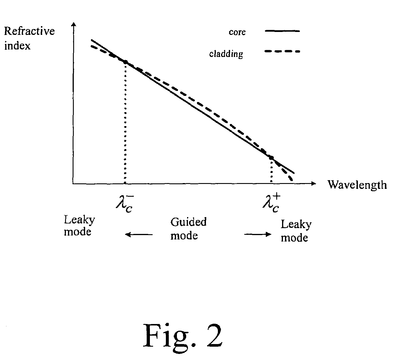
[0049]In the present invention, the theory of total internal refection (TIRF) is utilized. That is, the refractive index of a core of a fiber must be higher than that of a cladding of the fiber so that the signal light is able to be guided to propagate in the core. However, there are four situations with regard to the refractive indices of a core and a cladding of a fiber varying with the wavelength of the light, which are shown in FIG. 1 to FIG. 4, relating to the cases of a fiber-optic band-pass, a band-rejection, a short-pass and a long-pass filters respectively.

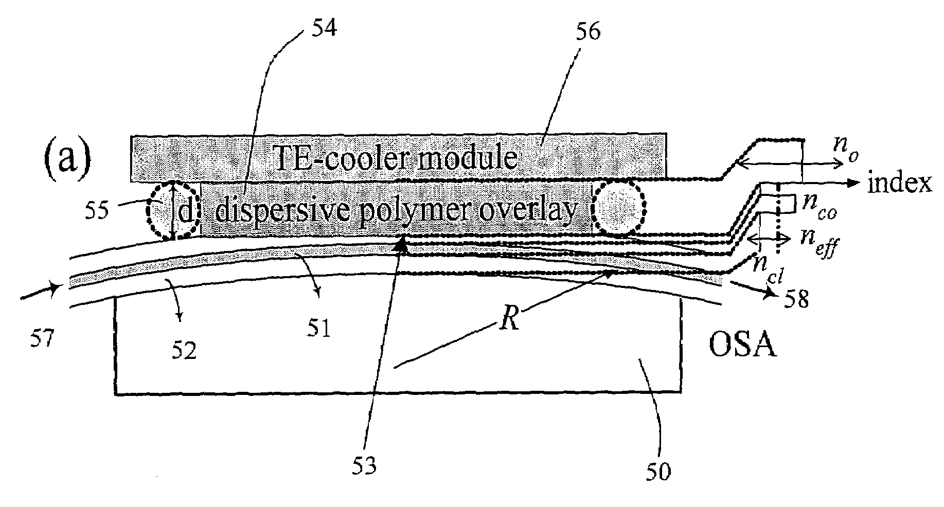
[0050]Instead of doping special constituents into the core and the cladding to fabricate dispersive fibers, the present invention takes steps therefor as follows. Please refer to FIG. 5. First, a normal fiber is arranged and fixed in a silicon V-groove 50 on a silicon substrate. The cladding 52 on the silicon substrate is then polished to show an evanescent-field 53. Different kinds of dispersive polymers 54 is positioned...


PUM


Abstract

A wide-band fiber-optic tunable filter is provided. Dispersive polymers with different dispersion characteristics and side-polished fibers are used to fabricate wide-band tunable band-pass filters, band-rejection filters, short-wavelength-pass filters or long-wavelength-pass filters. This kind of wide-band fiber-optic tunable fiber filters is able to be used in the applications of fiber-to-the-home (FTTH) system networks. It is also able to be used in the applications of sensitive temperature sensors, high-resolution fiber refractometers, gain-flattened filters, fiber modal filters and fiber mode-field expanders / condensers.

Description

FIELD OF THE INVENTION[0001]The present invention relates to a fiber-optic filter, especially to a wide-band fiber-optic tunable filter in the application of the fiber-to-the-home (FTTH) network of Tri-band system.BACKGROUND OF THE INVENTION[0002]Presently, various methods are developed for fabricating the fiber-optic filter. For example, in the case of U.S. Pat. No. 6,636,684B1, which is entitled “Dispersive Optical Fiber Using Binary Component Slica”, cores and claddings of fibers with different material dispersions are utilized to fabricate a fiber-optic filter. Besides, in the case of U.S. Pat. No. 5,673,342, which is entitled “Communication System Comprising A Low Cost Optical Filter”, a core and a depressed cladding of a fiber is utilized to fabricate a waveguide dispersion. However, these methods both need specialized kinds of fibers, which cost much and have high optical losses.[0003]Regarding the academic research, moreover, many efforts are also done for improving the fabr...

Claims


Application Information

Patent Timeline
IPC IPC(8): G02B6/26H01P1/20
CPCG02B6/02052G02F1/0118G02F1/0147G02F2203/055
Inventor CHI, SIENCHEN, NAN-KUANGTSENG, SHIAO-MIN
Owner NAT CHIAO TUNG UNIV
Why Eureka
Try Eureka