
Identifying the location of an asset

a technology of asset location and asset location, which is applied in the direction of burglar alarm mechanical actuation, data switching network, instruments, etc., can solve the problems of unacceptably high cost, inability to determine the specific location of assets within the reader's zone, and inability to determine the specific position of assets within that zone, so as to reduce the overall cost and reduce the processing requirements

Inactive Publication Date: 2006-12-26
HONEYWELL INT INC
View PDF64 Cites 49 Cited by
  • Summary
  • Abstract
  • Description
  • Claims
  • Application Information

AI Technical Summary

Benefits of technology

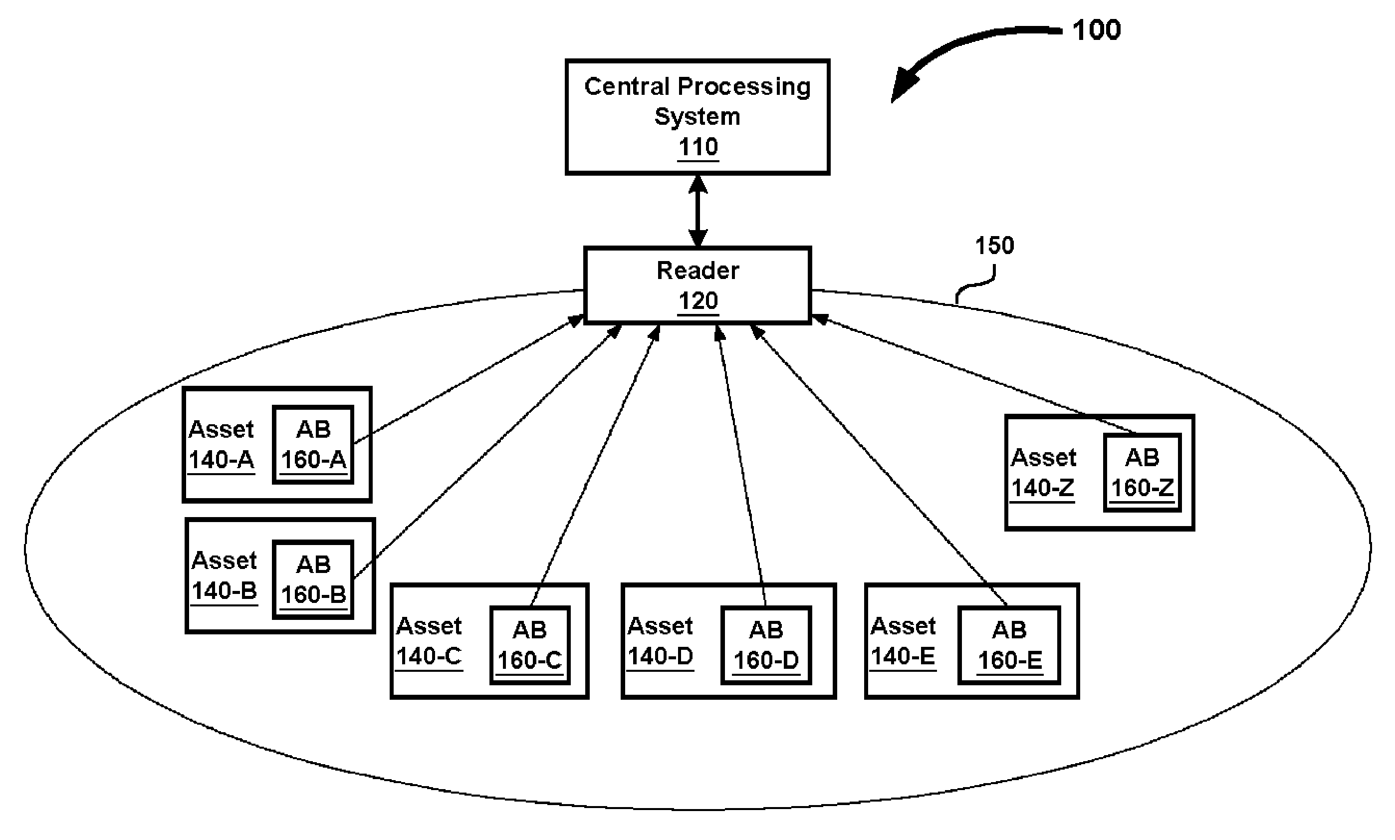
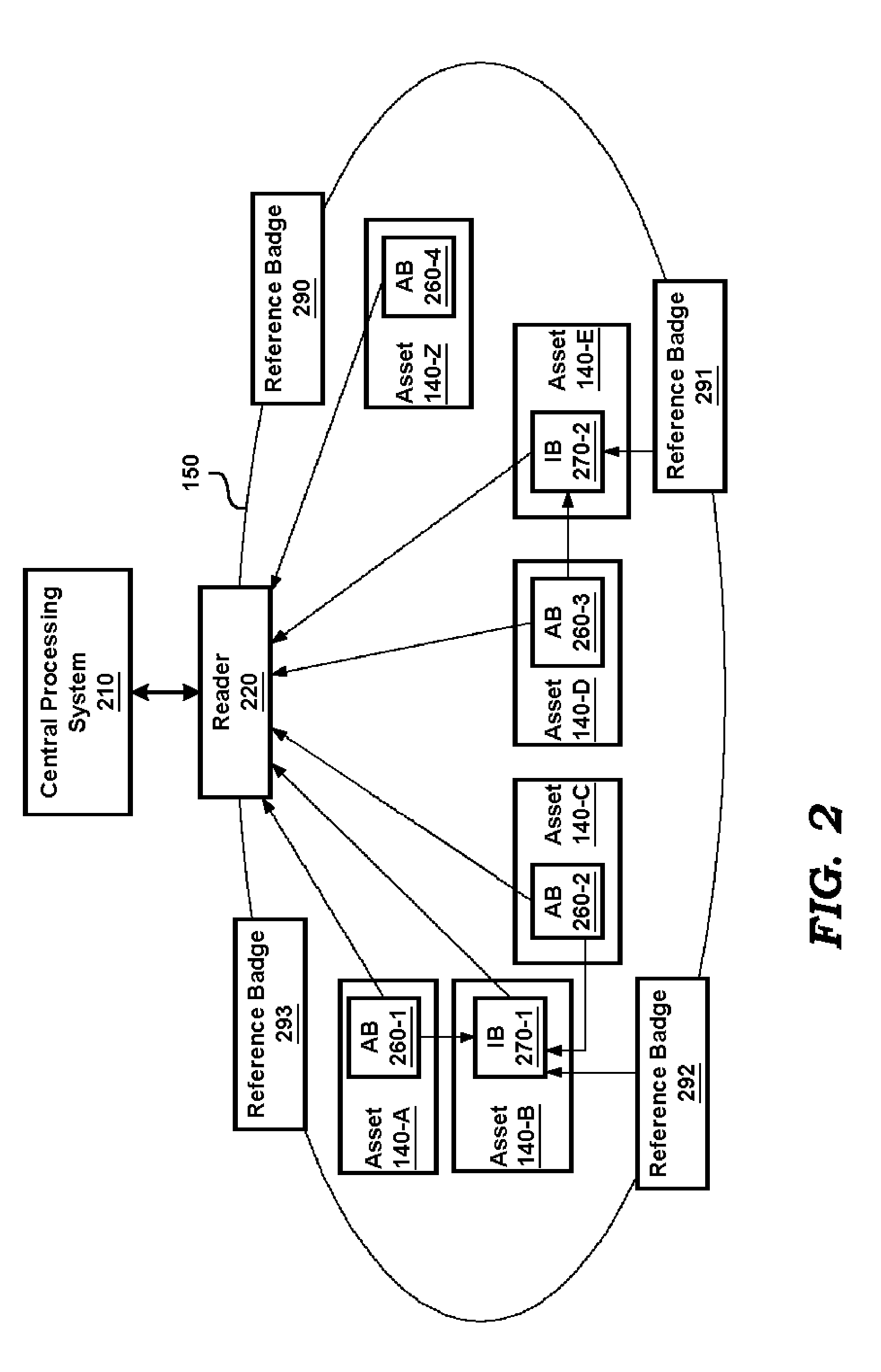
[0015]The approximate location of each of the assets attached to one of the component badges is deemed to be the same as the relative location of the active badge. As a result, the processing requirements on the processing system may be reduced. In addition, the component badges may be designed to transmit badge identifier using energy derived from signal transmissions from the active badges, and the overall cost may be reduced as a result as well.

Problems solved by technology

One problem with the above approach is that the specific position of the asset within that zone may not be identified even approximately.
Unfortunately, it may not be possible to determine the specific location of assets within a zone of the reader.
Unfortunately, implementation of GPS support in individual tags may lead to unacceptably high cost solutions.
On the other hand, approaches based on time of flight of signals may not be suitable in situations when assets are closely located since such techniques are generally based on measuring a round-trip time of a signal sent by a reader and reflected by the specific asset.
In particular, the reader may not be able to identify which specific one of the tags has reflected the signal, thereby posing challenges in determining the specific location of an asset of interest.
In addition, since all badges need to have support for cooperatively reflecting the signals sent by a reader, the total cost of such implementation may also be unacceptably high.

Method used


Image

  • Identifying the location of an asset
  • Identifying the location of an asset
  • Identifying the location of an asset

Examples


Embodiment Construction

1. Definitions

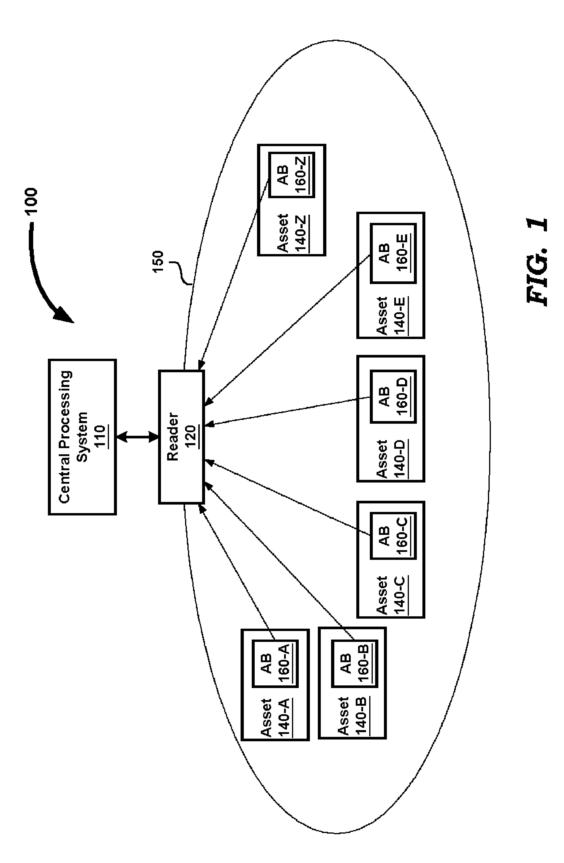
[0026]The following definitions are used in the subject patent application:Asset Badge: A badge attached to an asset. An asset badge transmits a self-identifier or badge identifier (any signal / data that uniquely identifies the asset badge) using a wire-less technology (e.g., based on infra-red signals).

[0027]Reference Badge: A badge whose location is predefined / identified (e.g., by placing the reference badge in a known location or by using technologies such as GPS) Intelligent Badge: A badge which can collect the self-identifiers of asset badges (including active badges, described below), reference badges and other intelligent badges within its (i.e., of the intelligent badge) zone. The collected identifiers are passed to a data processing system to determine the location of the badges.

[0028]Active Badge: A type of asset badge, which is associated with a group of assets. The active badge collects the identifiers of a group of component badges (defined below), and tran...


PUM


Abstract

According to an aspect of the present invention, an intelligent badge having the ability of collecting the identifiers of each of the badges located within the zone of the intelligent badge may be employed to identify the location of each badge. The central processing system determines the relative location of an asset by processing the sets of identifiers received from multiple intelligent badges. The relative location of an asset is determined by identifying at least one common badge identifier of a badge attached to a corresponding one of assets. The relative location of each asset may be determined with reference to known location of some badges by employing reference badges.

Description

BACKGROUND OF INVENTION[0001]1. Field of the Invention[0002]The present invention generally relates to asset locator systems, and more specifically to a method and apparatus for identifying the location of an asset.[0003]2. Related Art[0004]An asset, as used in the present application, generally refers to a property which can be moved from one location to another. For example, in the airline industry, passenger bags (assets) are transported across multiple locations (e.g., from check-in place to temporary storage place, to a sequence of flights, and then to check-out place in the destination location).[0005]There is a general need to identify the present location of an asset. In the airline example of above, it is desirable to know in which airport / storage place, etc., a specific baggage is present. The information may then be used to track the location of the asset, if such a need arises, as is well known in the relevant arts.[0006]A prior approach may attach a badge (“asset badge”...

Claims


Application Information

Patent Timeline
Patent Type & Authority Patents(United States)
IPC IPC(8): G06F19/00G06K19/06G06Q30/00G06Q90/00G08B13/14G06Q10/00
CPCG06Q10/08
Inventor CHAPPIDI, GOPINATHKORE, VINAYAK SADASHIV
Owner HONEYWELL INT INC
Learn More