Endotracheal catheter and manifold assembly with improved valve

Inactive Publication Date: 2006-12-26
AVENT INC
View PDF94 Cites 30 Cited by
  • Summary
  • Abstract
  • Description
  • Claims
  • Application Information

AI Technical Summary

Benefits of technology

[0006]The present invention provides an improved design for internal components for the catheter tube manifold assemblies, including the flap valve of respiratory suction catheter assemblies. The flap valve or other internal component is preferably formed with at least one protrusion on at least one surface such that each protrusion will aid in the positioning of the flap valve or other internal component. By forming the flap valve or other internal component with at least one protrusion sufficient to maintain a space between the flap valve and the distal portion of a catheter that may translate within the assembly, the integrity and working condition of the flap valve or other internal component is protected while improving the cleaning of the assembly. This improved flap valve or other internal component will minimize the amount of mucus and similar secretions that collects or coats the distal surface of the flap valve during retraction or withdrawal of the catheter from the assembly and thus improves removal of mucus and other secretions from the distal tip of the catheter. By automatically separating or otherwise partitioning at least a portion of the assembly to form a cleaning area from the ventilation circuit, each protrusion formed or otherwise attached to the flap valve or other internal component will cause a more efficient cleaning to be affected by ensuring that the majority of the mucus or similar secretions are withdrawn with the catheter into this cleaning area.
[0007]Various of the above and other objects of the invention are realized in specific illustrated embodiments of an improved respiratory suction catheter apparatus set forth more fully herein and claimed below. The embodiments of an improved respiratory suction catheter apparatus typically include a manifold for attachment to an artificial airway, such as an endotracheal tube, to form a ventilation circuit, a catheter which is displaceable through the manifold and into the artificial airway to suction secretions from the artificial airway and lungs, and a variation of the flap valve or other internal component valve mechanism of the present invention disposed adjacent the ventilation circuit to minimize the air drawn from the ventilation circuit of a patient while the catheter is being cleaned.
[0008]In accordance with one aspect of the invention, the flap valve or other internal component valve mechanism is configured to engage the catheter as it is withdrawn through the manifold to thereby minimize the amount of mucus and similar secretions that may otherwise be scraped onto a distal surface of the flap valve. This flap valve may be configured to lock in a closed position when it is pulled toward the withdrawn catheter to thereby maintain a selective isolation or separation between the catheter tip and the airway through the manifold. Using an air makeup, to allow makeup air into the catheter and thereby ensure proper evacuation of secretions and any liquid used to clean the assembly, may enhance this flap valve or other internal component.
[0009]In a preferred embodiment of the present invention, each protrusion may be connected by a bridge that improves the interaction between the translating catheter and the protrusion formed on flap valve such that withdrawal or retraction of the catheter does not cause mucus or similar secretions from being scraped onto the flap valve in a manner that impedes cleaning of the assembly.

Problems solved by technology

Moreover, because the endotracheal tube may be left in the patient for a prolonged period of time, it will become necessary to service these endotracheal catheter tube and manifold assemblies to replace, repair, refit, or otherwise manipulate the assembly.
This is particularly important because patients on mechanical ventilation often have compromised immune systems.

Method used


Image

  • Endotracheal catheter and manifold assembly with improved valve
  • Endotracheal catheter and manifold assembly with improved valve
  • Endotracheal catheter and manifold assembly with improved valve

Examples


Embodiment Construction

[0037]Reference will now be made to the drawings in which the various elements of the present invention will be given numeral designations wherein like numerals are used to designate like materials throughout. It is to be understood that the following description is only exemplary of the principles of the present invention, and should not be viewed as narrowing the pending claims. Those skilled in the art will appreciate that aspects of the various embodiments discussed may be interchanged and modified without departing from the scope and spirit of the invention. Moreover, the use of reference numerals in each Figure is only to show a preferred embodiment of the corresponding structure and is not intended to limit the scope of the invention as claimed herein.

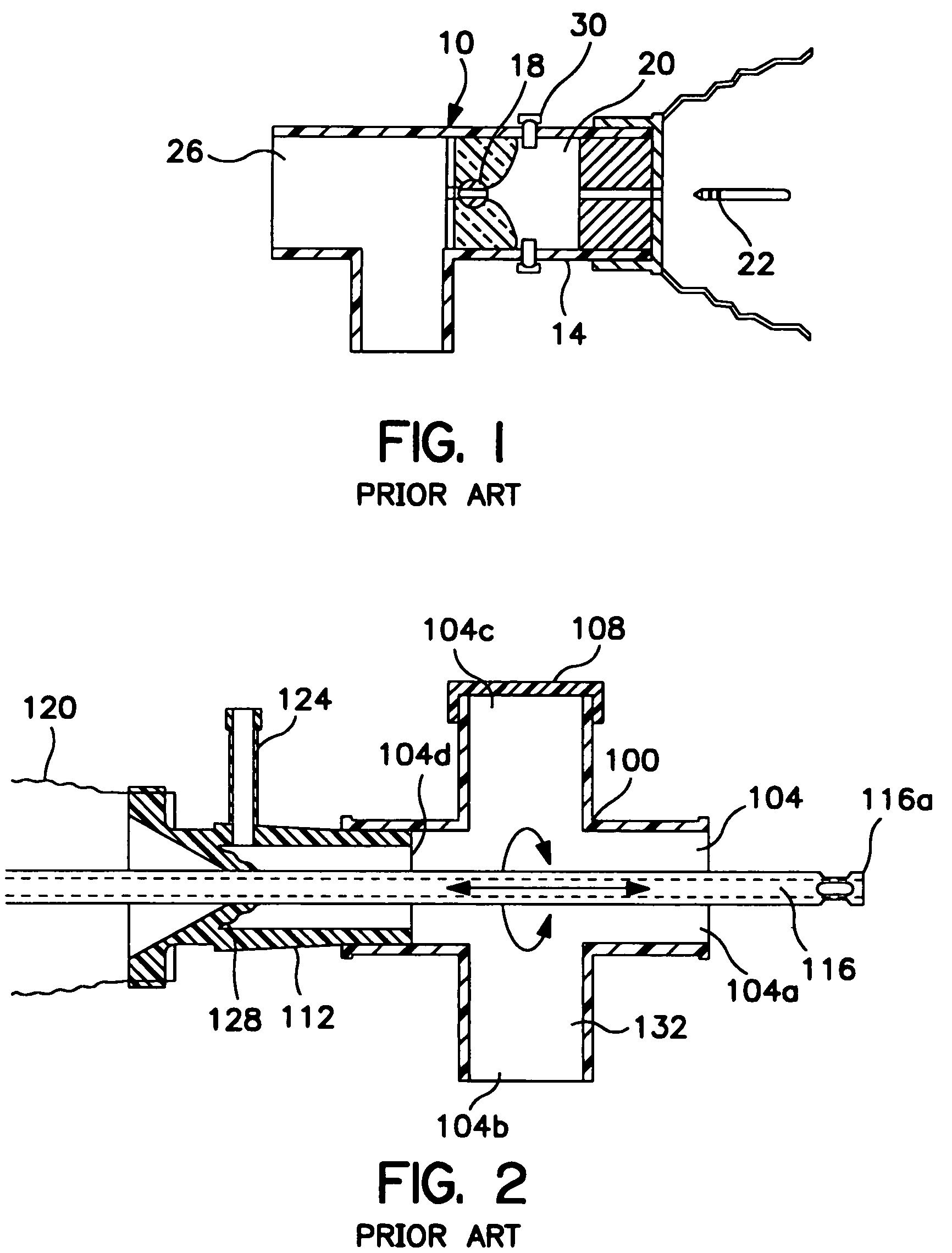
[0038]Referring to FIG. 1, there is shown a cross-sectional view of a manifold 10 and catheter cleansing mechanism 14 in accordance with the teachings of the prior art. The manifold has a valve mechanism in the form of a rotatab...


PUM


Abstract

The present invention relates to an improved flap valve or other internal component for use with respiratory suction catheter and manifold assemblies. This flap valve or other internal component provides the assembly with an improved mechanism for cleaning the tip of the catheter without drawing an excessive amount of air from the respiration circuit to which the endotracheal catheter is attached. More specifically, the present invention relates principally to a closed suction endotracheal catheter system which provides improved cleaning of the catheter while minimizing air drawn from the patient's ventilation circuit by providing at least one protrusion on at least one surface of the flap valve or other internal component. By using a flap valve or other internal component with at least one protrusion, the flap valve or other internal component is strengthened and designed to prevent the flap from scraping mucus or other secretions from the catheter onto the distal surface of the flap during retraction.

Description

FIELD OF THE INVENTION[0001]The present invention relates to an improved flap valve or other internal component for use with respiratory suction catheter and manifold assemblies by providing at least one protrusion on at least one surface of the flap valve or other internal component that may aid in reducing or preventing mucus and similar secretions from collecting on the distal surface of the flap valve or other internal component during retraction of the catheter, thus improving the cleaning of the assembly.BACKGROUND OF THE INVENTION[0002]In the past twenty years, the medical industry has seen an increased interest in closed suction catheter systems to create artificial airways. Such systems were disclosed in U.S. Pat. No. 3,991,762 (“Radford”), which provided for a catheter within a protective sleeve such that the catheter is only advanced when suctioning is desired. Furthermore, U.S. Pat. No. 4,569,344 (“Palmer”), offered an improved system to reduce the risk of cross-contamin...

Claims


Application Information

Patent Timeline
IPC IPC(8): A61M16/00A61M16/04A61M16/20
CPCA61M16/0463A61M16/04
Inventor CRUMP, CHET M.MADSEN, EDWARD B.
Owner AVENT INC
Why Eureka
Try Eureka