
Footwear system

a shoe and shoe technology, applied in the field of shoes, can solve the problems of high production cost of the bladder, inability to meet the needs of consumers, so as to improve the leverage of the ground contact, reduce the compression of the passageway, and provide visibility to consumers

Active Publication Date: 2006-12-26
TRANSFORM SR BRANDS LLC
View PDF35 Cites 94 Cited by
  • Summary
  • Abstract
  • Description
  • Claims
  • Application Information

AI Technical Summary

Benefits of technology

[0010]It is another object of the present invention to provide a number of passageways between outsole and midsole cavities that are formed as bulges to avoid possible blockage during production or use.
[0011]It is yet another object of the present invention to provide a shoe that is stable at point of impact and has a footwear system that imparts energy absorption to the foot upon impact.
[0014]It is a further object of the present invention to provide an outsole made in a number of pieces to be applied to a midsole with a sole unit having a number of bulges and for the outsole and midsole connection process not to block any passageways formed between the bulges by the manufacturing process or by compression.
[0015]It is still a further object of the present invention to provide a number of bulges that extend the cushioning effect of bulges and passageways beyond the metatarsal region and into the toe region of a sole unit without having an extended portion that could potentially cause tripping.
[0016]It is yet a further object of the present invention to provide a stabilizing block about a heel of an outsole that extends beyond a periphery of the heel to improve leverage in ground contact.
[0017]It is another object of the present invention to provide a transparent shank to cover the passageways in the midsole at a midfoot region to reduce compression of the passageways and provide visibility to consumers.

Problems solved by technology

However, the bladder also has a number of detriments that outweighs the effectiveness of the cushioning.
First, the bladder is expensive to manufacture, and requires precision when the bladder is installed in the pocket of the shoe.
If improperly and imprecisely installed in the pocket, the bladder may not cushion the foot.
Additionally, increased material costs must be borne by the manufacturer and consumer.
These costs are attributed to forming the shoe with the bladder.
Further, additional increased labor costs result.
This increased labor costs are attributed to placing the bladder in the pocket at a precise pre-selected location of the pocket, which is time consuming, and sealing the pocket with the bladder in the correct pre-selected location of the pocket to facilitate cushioning.
These bladder installation operations are labor, and time intensive, and increase the cost of the shoe.
When running or walking, this collapse in height may result in the foot in the shoe dropping suddenly from the first height to the second height upon impact with the ground.
As such, the bladder creates an unstable sensation during impact.

Method used


Image

  • Footwear system
  • Footwear system
  • Footwear system

Examples


Embodiment Construction

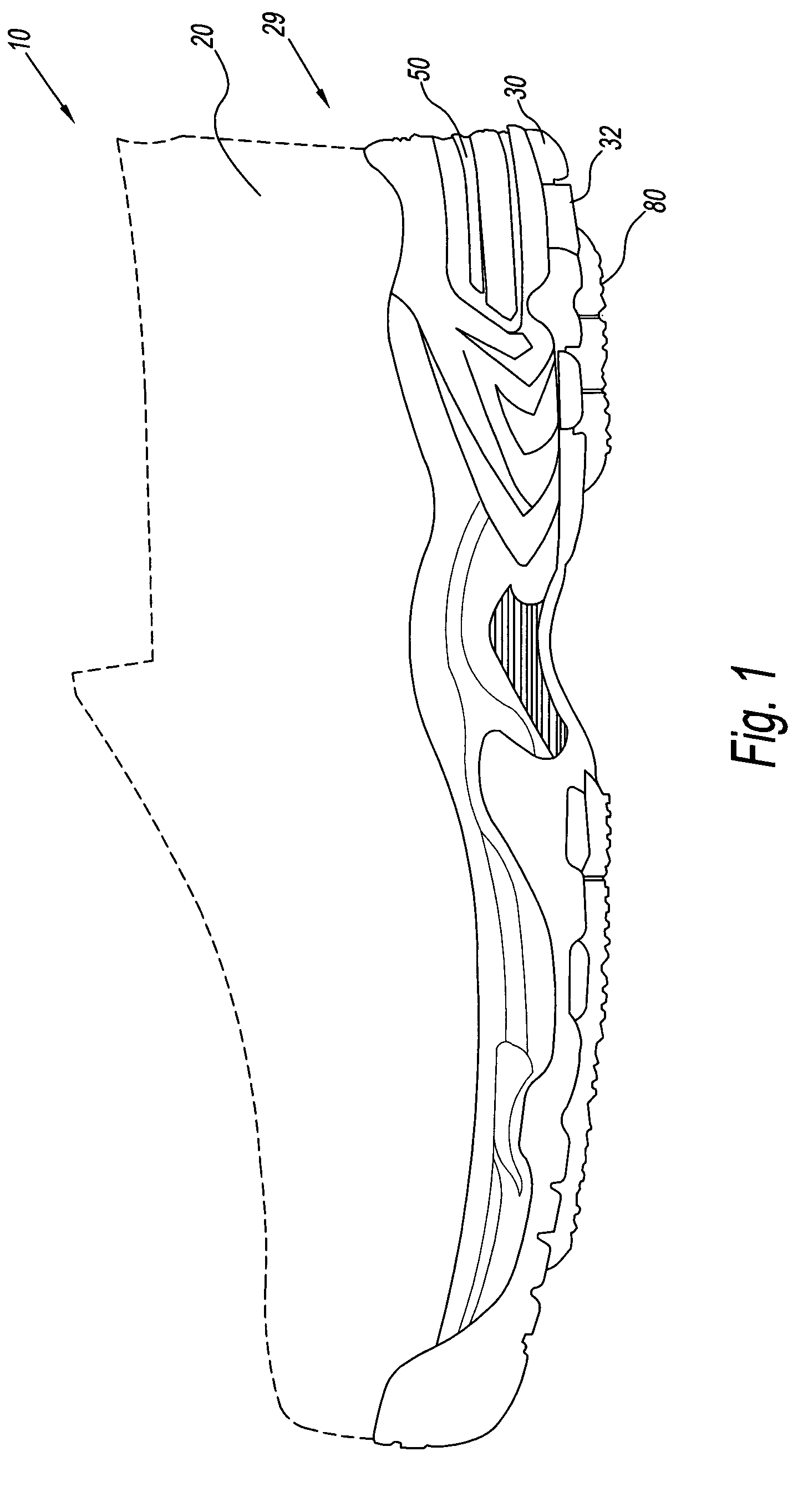
[0029]Referring to the drawings and, in particular, FIG. 1, there is provided a shoe according to the present invention generally represented by reference numeral 10. The shoe 10 is shown as an athletic shoe. However, one skilled in the art should appreciate that the shoe may be any type of shoe known in the art, including but not limited to, a dress shoe, a boot, a cross training shoe, a running shoe, a sneaker, a flat, a high heeled shoe, an overshoe, a pump, a loafer, a moccasin, a padded sock, a slipper, or any other shoe for athletic, dress or comfort.

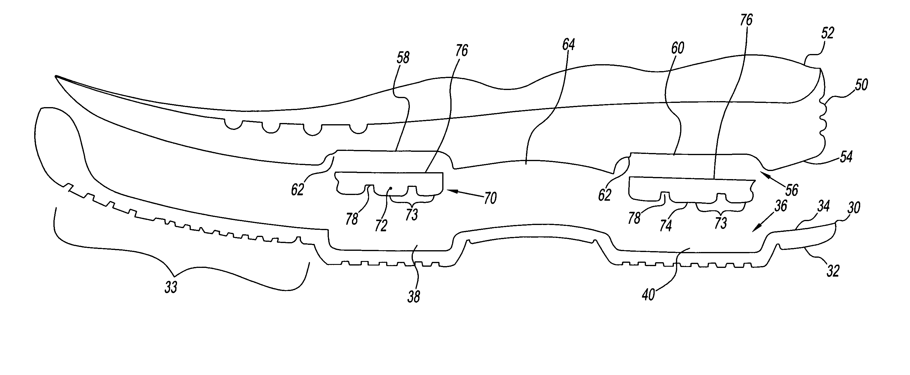
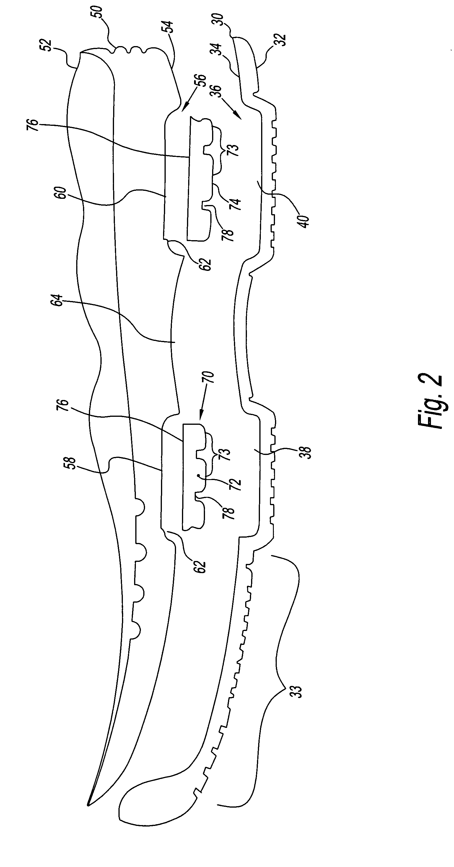
[0030]The shoe 10 has an upper 20 connected to a sole unit 29. The sole unit 29 is a combination of the midsole 50 and an outsole 30. The upper 20 is a portion of the shoe 10 covering a foot above the sole unit 29. The sole unit 29 has the ground contacting outsole 30 including a number of air bulges 80. The number of air bulges 80 extend toward the ground or groundwardly from the outsole 30. Preferably, the number of air bulges 8...


PUM


Abstract

A footwear system has a sole unit with a number of cavities formed between a midsole and an outsole. The cavities are complementary to one another to form groundward oriented air bulges in the outsole that are connected by a passage formed in the midsole. The passage permits movement of air between the cavities during use of the footwear system in a shoe.

Description

BACKGROUND OF THE INVENTION[0001]1. Field of the Invention[0002]The present invention relates to shoes. More particularly, the present invention relates to a shoe having a footwear system with an air bulge formed by a midsole and an outsole of the shoe.[0003]2. Description of the Related Art[0004]Shoes having cushioning members disposed under a wearer's foot are known in the art, for example U.S. Pat. No. 5,701,687 to Schmidt, U.S. Patent Nos. 5,896,608, 5,279,051, 5,060,401, 5,005,299, 5,440,826 to Whatley, U.S. Pat. No. 4,741,114 to Stubblefield, U.S. Pat. No. 4,706,316 to Tanzi, U.S. Pat. No. 4,132,016 to Vaccari, U.S. Pat. No. 5,595,002 to Slepian, U.S. Pat. No. 4,881,329 to Crowley, U.S. Pat. No. 4,566,206 to Weber, U.S. Pat. No. 4,771,554 to Hannemann, U.S. Pat. No. 4,910,884 to Lindh, U.S. Pat. Nos. 5,926,974, 6,018,889, 6,226,896 to Friton, U.S. Pat. No. 6,029,962 to Shorten, U.S. Patent Nos. 5,524,364, 4,577,417, 5,375,346, 5,545,463 and 5,416,986 to Cole, U.S. Pat. Nos. 5,...

Claims


Application Information

Patent Timeline
Patent Type & Authority Patents(United States)
IPC IPC(8): A43B13/20
CPCA43B13/20A43B7/144A43B7/1445A43B13/127A43B13/186
Inventor WHATLEY, IAN
Owner TRANSFORM SR BRANDS LLC
Learn More