Eureka AIR delivers breakthrough ideas for toughest innovation challenges, trusted by R&D personnel around the world.

Holographic data-storage medium

a technology of holographic data and storage media, which is applied in the field of holographic data storage media, can solve the problems of loss of data, impairment of the resolution of reconstructed holographic images, and material change in the polymer film leading to local change in the interface structure, etc., and achieves the effect of reducing the cost of production, facilitating the reading out of stored holographic information, and simplifying the operation of setting the focus

Inactive Publication Date: 2006-12-19
TESA SCRIBOS
View PDF200 Cites 6 Cited by
  • Summary
  • Abstract
  • Description
  • Claims
  • Application Information

AI Technical Summary

Benefits of technology

[0007]Since the polymer film is set up as a top layer of the data storage medium, it can serve as the exposed outer side of the data storage medium and protects the generally relatively sensitive absorber layer located underneath. Furthermore, the changes in the polymer film which are effected by heating and using which holographic information is stored are primarily localized in the vicinity of the absorber layer, as explained in more detail further below. Therefore, this region of the polymer film provided with the stored information is likewise located in a protected zone. Undesired influences on the exposed outer side, such as scratches, therefore generally do not have any further effect and, above all, do not lead to a loss of data or to faults when putting information into the data storage medium.
[0008]The holographic data storage medium according to the invention is simply constructed, since an additional protective device can generally be dispensed with, and can therefore be produced inexpensively.
[0009]An adhesive layer is preferably arranged underneath the absorber layer, and makes it possible to stick the holographic data storage medium onto an object. If the adhesive layer is located immediately underneath the absorber layer, it simultaneously protects the absorber layer and the adjacent region of the polymer film with stored holographic information. The adhesive layer can, for example, contain an adhesive compound comprising an aqueous acrylate emulsion or can consist of functionalized poly(meth)acrylate. Other materials can also be used for the adhesive layer. One preferred thickness of the adhesive layer is about 20 μm, but other thicknesses are also possible.
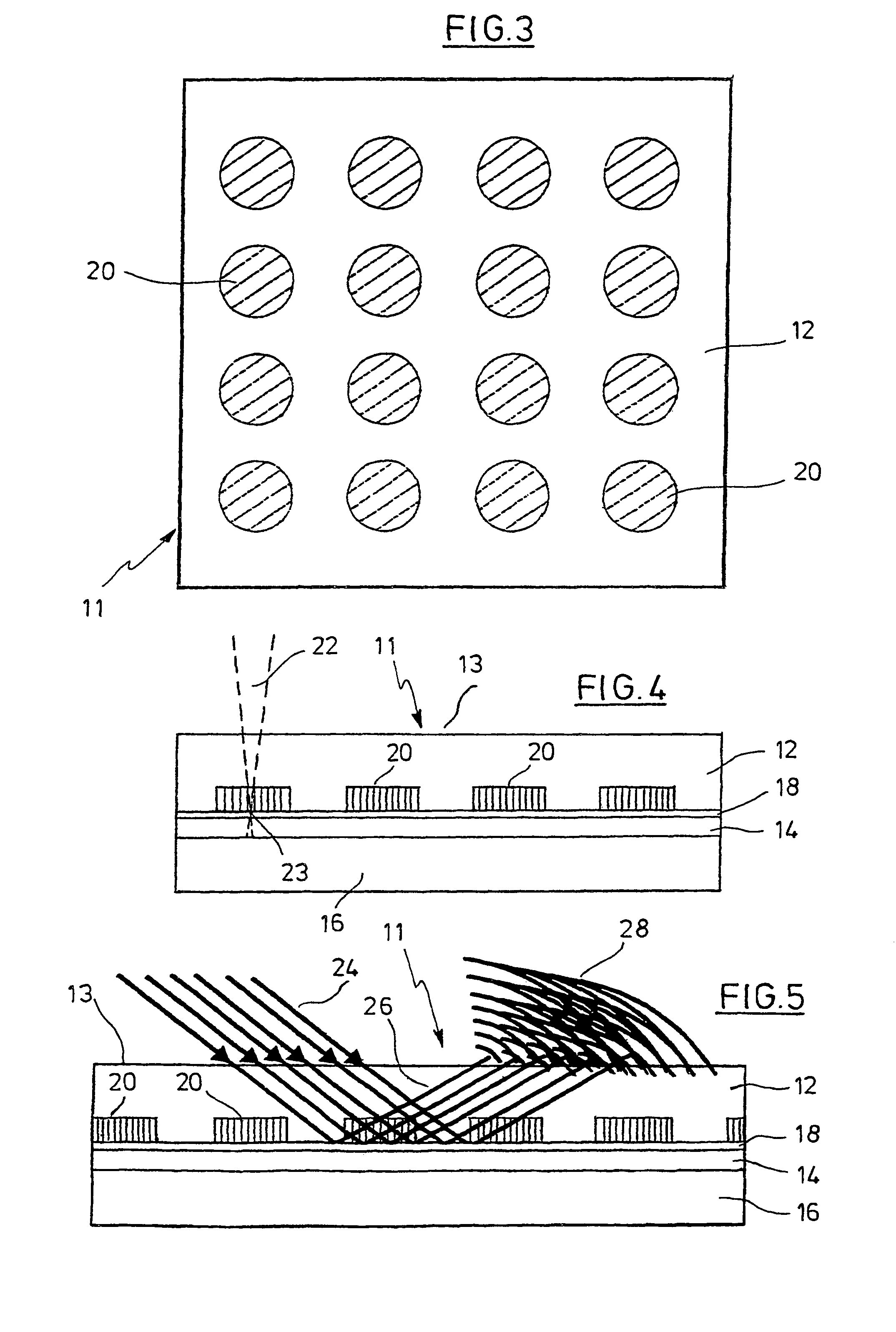
[0010]In an advantageous refinement of the invention, a partly transparent reflective layer is arranged between the storage layer and the absorber layer. The reflective layer can have aluminum and preferably has a thickness in the range from 1 nm to 50 nm, other thicknesses also being possible. It is partly transparent, in order that the write beam penetrates as far as the absorber layer when information is being put in. Since the reflective layer is thin, it virtually does not hinder the discharge of heat to the polymer film. The reflective layer makes it easier to read out the stored holographic information in reflection, which represents a beneficial geometry in most applications. This is explained further below using examples. Furthermore, the reflective layer simplifies the operation of setting the focus of the write beam (see below).

Problems solved by technology

In particular if the laser beam is radiated in briefly (pulsed), the material change in the polymer film leading to the local change in the interface structure is limited to a very small volume, on account of the generally poor thermal conductivity of the polymer (or of a very thin reflective layer).
If, in spite of the protection by the exposed outer side of the polymer film of the regions of the data storage medium serving to store information, damage nevertheless occurs then, as opposed to a conventional data storage medium, this generally does not lead to a loss of data but merely to impairment of the resolution of the reconstructed holographic image when reading out the information.

Method used


Image

  • Holographic data-storage medium
  • Holographic data-storage medium
  • Holographic data-storage medium

Examples


first embodiment

[0040]FIG. 1 illustrates, in a schematic way and not to scale, a detail from a holographic data storage medium 1 in longitudinal section. The data storage medium 1 contains a polymer film 2 which serves simultaneously as a storage layer and as a top layer with an exposed outer side 3. In the exemplary embodiment, the polymer film 2 is self-supporting. Arranged underneath the polymer film 2 and adjacent to the polymer film 2 is an absorber layer 4 with an absorber dye. Underneath it there is an adhesive layer 6 which, in the delivered state of the data storage medium 1, is preferably covered by a film that can be pulled off or silicone paper. The terms “above” and “below” relate here and in the following text to the illustration in the figures; however, the data storage medium can also be arranged in any other orientation.

[0041]In the exemplary embodiment, the polymer film 2 is a biaxially oriented film of polypropylene (BOPP) with a thickness of 35 μm. Thinner or thicker films are ...

second embodiment

[0045]FIG. 2 is an illustration similar to FIG. 1 of a holographic data storage medium, which is designated 1′ here. Just like the data storage medium 1, the data storage medium 1′ has a polymer film 2 (here made of polyethylene terephthalate), which is set up as a storage layer and top layer with an exposed outer side 3, an absorber layer 4 and an adhesive layer 6. In addition, there is a reflective layer 8 between the polymer film 2 and the absorber layer 4.

[0046]In the exemplary embodiment, the reflective layer 8 consists of aluminum vapor-deposited on the underside of the polymer film 2 with a thickness such that the result is a transmission of 50%. Preferred layer thicknesses lie in the range from 1 nm to 50 nm, but smaller or larger values are also possible. Given such a low thickness, the reflective layer 8 is partly transparent, so that a write beam aimed at the outer side 3 of the polymer film 2 (for example from a laser lithograph, see below) can pass through the reflectiv...


PUM

PropertyMeasurementUnit
thicknessaaaaaaaaaa
thicknessesaaaaaaaaaa

Abstract

In an example holographic data storage medium, which has a polymer film which serves as a storage layer and can be changed locally by heating, the polymer film is set up as a top layer of the data storage medium. Arranged underneath the polymer film is an absorber layer which has an absorber dye. The absorber dye is set up to at least partly absorb a write beam serving to put information in and to discharge the heat produced in the process at least partly locally to the polymer film. In an advantageous refinement of the example data storage medium, there is an adhesive layer underneath the absorber layer and a partly transparent reflective layer between the polymer film and the absorber layer.

Description

[0001]This application is the U.S. national phase of international application PCT / EP02 / 01951, filed in English on 25 Feb. 2002, which designated the U.S. PCT / EP02 / 01951 claims priority to DE Application No. 101 28 902.2 filed 15 Jun. 2001. The entire contents of these applications are incorporated herein by reference.BACKGROUND AND SUMMARY[0002]The invention relates to a holographic data storage medium which, for example, can be used for storing pictorial data such as photographs, logos, text and so on but also for the storage of other data.[0003]Contained in a hologram, distributed over the area of the hologram, is optical phase information about an object, from which, when irradiated with light, and in particular coherent light from a laser, an image of the object can be reconstructed. Holograms are used in many and various ways in technology, for example in the form of largely forgery-proof identifiers. Identifiers of this type will be found, for example, on credit cards or chec...

Claims


Application Information

Patent Timeline
Patent Type & Authority Patents(United States)
IPC IPC(8): G03H1/02G03H1/04G03H1/18G11B7/0065G11B7/24G11B7/258G11B7/2585
CPCG03H1/0244G03H1/0256G11B7/0065G11B7/24G11B7/245G11B7/252G03H2001/0264G03H2001/0478G03H2224/06G03H2240/24G03H2250/36G03H2260/61G11B7/256G11B7/2585G03H2240/11
Inventor LEIBER, JORNBLAZEJEWSKI, ANNANOEHTE, STEFFENSTADLER, STEFANDIETRICH, CHRISTOPHGERSPACH, MATTHIAS
Owner TESA SCRIBOS
Why Eureka
Eureka Blog
Learn More