Module

a module and module technology, applied in the field of modules, can solve the problems of displacement of nails, insufficient stroke or displacement of nails, disassembly of latches with mounting devices, etc., and achieve the effects of reducing the number of parts, facilitating assembly, and reducing the friction between the case and the metal fitting

Inactive Publication Date: 2006-12-19
FUJITSU LTD
View PDF4 Cites 0 Cited by
  • Summary
  • Abstract
  • Description
  • Claims
  • Application Information

AI Technical Summary

Benefits of technology

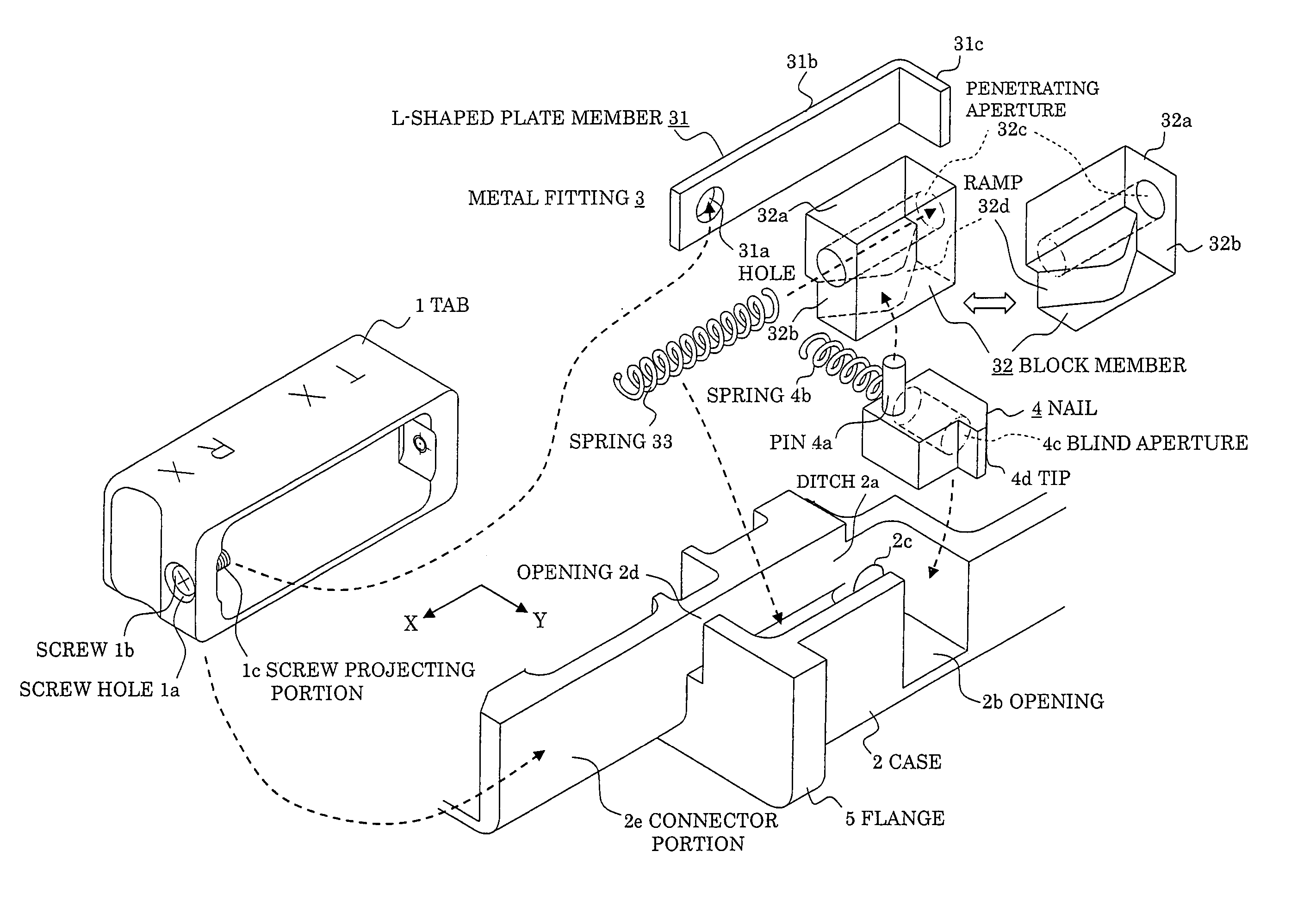
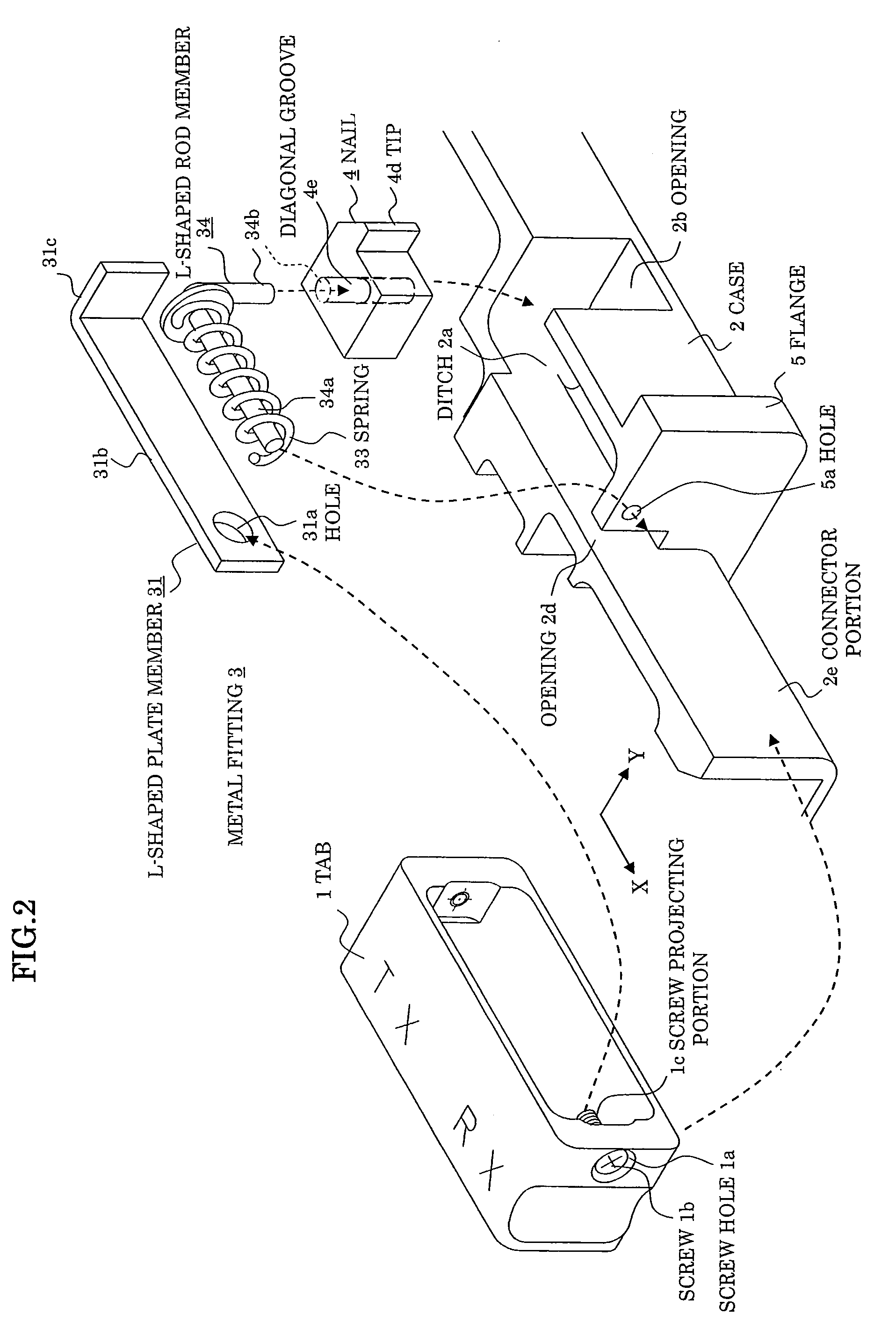
[0027]It is accordingly an object of the present invention to provide a module having a latch structure which enables frictions between a case and a metal fitting to be lowered, a displacement (amount) of a nail for engaging a latch between a mounting device and the case to be enlarged, the assembly to be easily made, and the number of parts to be reduced.
[0030]Namely, a metal fitting held in a ditch structure provided in a case employs a plate member thinner than the length of a projecting portion of a tab, and is provided with a hole only for loosely engaging or hooking the projecting portion in the plate member. When the tab is pulled in the above-noted X direction, a substantial component of the pulling force is converted (XX directional conversion) into a force component in Y direction perpendicular to X direction to be provided to a nail, so that a wobbly condition in X direction can be absorbed and a displacement in Y direction can be sufficiently secured, whereby the XY conversion is enabled in a state where unnecessary frictions between the ditch structure and the metal fitting are reduced, facilitating the engagement / disengagement with the mounting device.
[0046]According to the present invention, it becomes possible to convert a force when pulling the tab into a latching displacement of the nail in a perpendicular direction through the metallic fitting without wastes, thereby easily disengaging the latch with the mounting device. Because of less frictions between the metal fitting and the case, the members do not wear out and the lives thereof are extended. Since the precision of the engaging face of the tab or metal fitting is eased, the assembly is facilitated. Also, common use of the spring members enables the number of parts to be reduced and the cost to be lowered.

Problems solved by technology

(1) Since the tab is fixed with the metallic fitting by screws, even a little displacement of the pulling direction of the tab from X direction will effect on the force component toward Y direction, which makes the stroke or displacement of the nail insufficient, disabling the latch with the mounting device to be disengaged.
Frequently repeated operations of the tab will loose the screws to decline the tab and make members rub each other and difficult to be moved, which will also reduce the displacement of the nail in Y direction.
Furthermore, mutual rubs between members will shorten the life due to wear.
Therefore, the opening angle of the tab will be varied to worsen the movement of the nail due to the contact with the inside face of the ditch of the case, resulting in a difficulty in assembly.
(4) There are a large number of parts such as springs for moving the nail, springs for returning the tab, and a metal fitting for transferring forces, which becomes a factor of cost increases.

Method used


Image

  • Module
  • Module
  • Module

Examples


embodiment (

4)

[0081]FIG. 4 shows an embodiment (4) of a module according to the present invention, which is different from the above-noted embodiments (1)–(3) in that the metallic fitting 3 only employs a leaf spring 37 that is one member. Namely, this metallic fitting 3 is composed of a bended portion 37b in a mild R-shape having a hole 37a loosely engaging the screw projecting portion 1c, an L-shaped portion 37b, and a coupling portion 37c for coupling the bended portion 37b and the L-shaped portion 37d where the leaf spring 37 is folded at a near center by 150–170°. The L-shaped portion 37d is inserted into a space between the pin 2f provided in the ditch 2a, the flange 5, and the case 2 to fix the leaf string 47. In the same manner as the first portion 36a of a leaf string 36 in the above-embodiment (3), the coupling portion 37c engages with a pin 4a provided in the nail 4.

[0082]The operation of the latching structure thus assembled will now be described referring to FIGS. 5A and 5B.

[0083]F...


PUM


Abstract

A module inserted / withdrawn into / from a mounting device and latched by the mounting device upon insertion, in which a tab disengages a latch with the mounting device by being pulled in the withdrawing direction, a case has an opening on both sides and supporting the tab, a nail goes in / out of the openings of the sides in the inserting direction of the case to engage a latch with the mounting device, a metal fitting is held in a ditch structure provided in the case, and the metal fitting has a hole for loosely engaging a projecting portion provided in the tab in a plate member thinner than a length of the projecting portion and converts a force component in the withdrawing direction applied to the tab through the hole into a force component in a direction substantially perpendicular to the withdrawing direction to displace the nail, thereby disengaging the latch with the mounting device.

Description

BACKGROUND OF THE INVENTION[0001]1. Field of the Invention[0002]A present invention relates to a module, and in particular to a latch structure in a module such as a pluggable optical module whose outer structure is prescribed according to MSA (Multi Source Agreement).[0003]2. Description of the Related Art[0004]A pluggable optical module is generally known as an optical module which can be easily inserted / withdrawn (or mounted / demounted, mated / demated, engaged / disengaged) into / from rails, connectors, etc. on a mounting device for the module, one example of which is shown in FIGS. 7 and 8.[0005]FIG. 7 shows, an exterior squint view of such a module, which is schematically composed of a tab (or pinch, lug) 1 and a case (housing) 2 and a lid 11. The lid 11 is a roof covering the case 2 and is provided with a radiator 11a. To this case 2, a nail 4 is accessible for engaging a latch between the module and a mounting device (not shown), namely the nail 4 goes in or goes out of the case 2...

Claims


Application Information

Patent Timeline
Patent Type & Authority Patents(United States)
IPC IPC(8): G02B6/36G02B6/42G02B6/00
CPCG02B6/4201G02B6/4292G02B6/4261
Inventor OKUSHIMA, HIROKI
Owner FUJITSU LTD
Why Eureka
Try Eureka