Electropneumatic double control valve comprising a sealing arrangement

Active Publication Date: 2006-12-19
KNORR-BREMSE SYST FUER NUTZFAHRZEUGE GMBH
View PDF11 Cites 2 Cited by
  • Summary
  • Abstract
  • Description
  • Claims
  • Application Information

AI Technical Summary

Benefits of technology

[0011]An advantage of the inventive sealing arrangement lies in the fact that, owing to the individual sealing components being one piece, they cannot be forgotten during assembly. In addition, the one piece design of the sealing arrangement offers ideal conditions for automating the assembly process. The flexibility in spacing the two sealing ring segments makes it easy to compensate for the casting-induced tolerances at the relay valve housing and/or the pilot valve housing. The invention makes it possible to compensate for the tolerances with the elastically flexible footbridges. In this manner the tolerances can be balanced without hardly any force.
[0012]According to another embodiment of the invention, at least one o

Problems solved by technology

However, the pneumatic drive is usually used only for safety in the case that the electric drive fails.
In casting the common relay valve housing and also the pilot valve housing connected thereto, there is the problem that the exact relative position of both adjacent control chambers cannot be reliably guaranteed.
Consequently the result can be an unfavorable chain of tolerances, so that the tightness between the relay valve housing and the pilot valve housing is not always guaranteed.
In addition, individual sealing rings are often forgotten during manual assembly so that the resulting cost of reworking is high.

Method used


Image

  • Electropneumatic double control valve comprising a sealing arrangement
  • Electropneumatic double control valve comprising a sealing arrangement
  • Electropneumatic double control valve comprising a sealing arrangement

Examples


Embodiment Construction

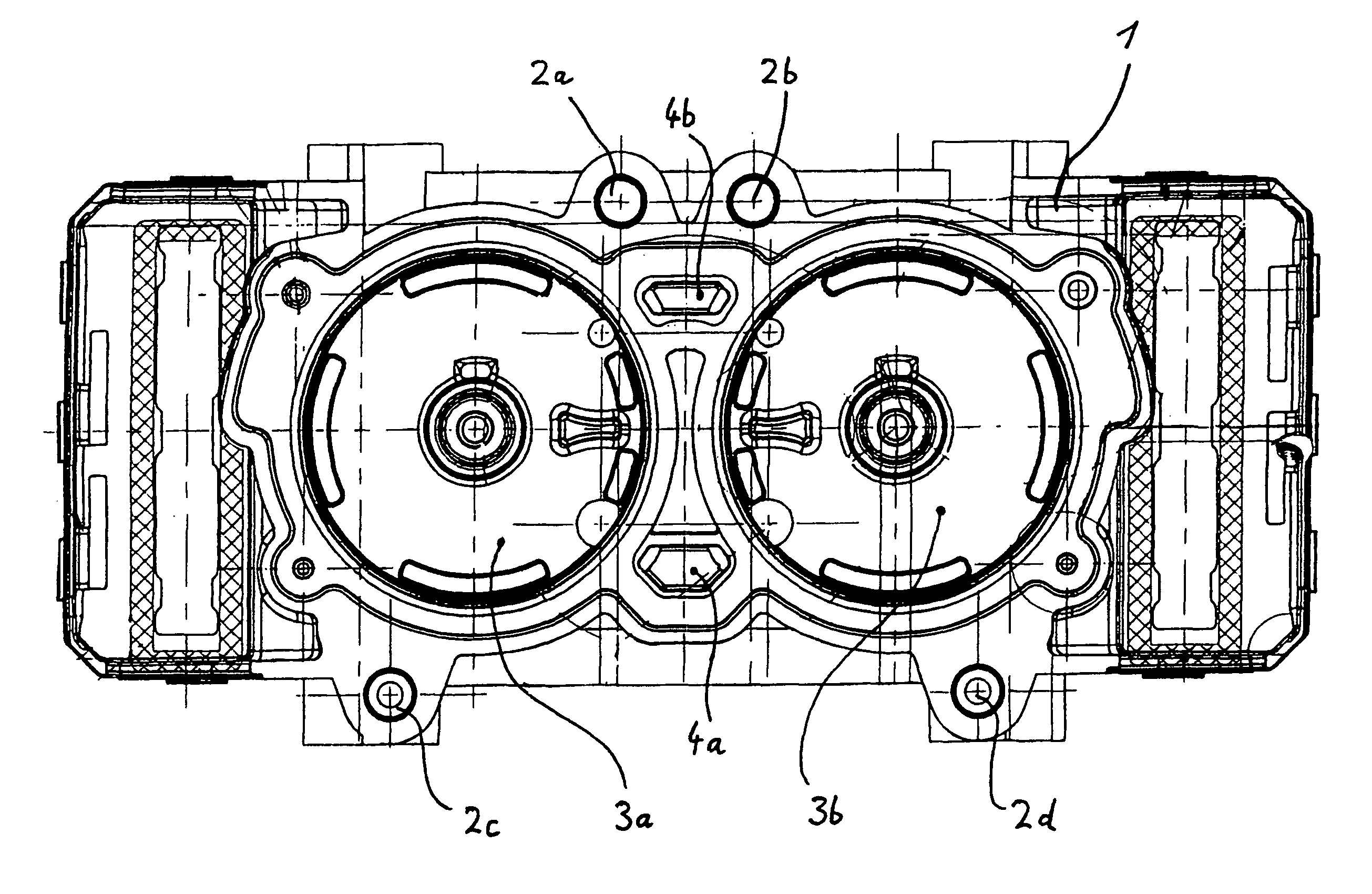
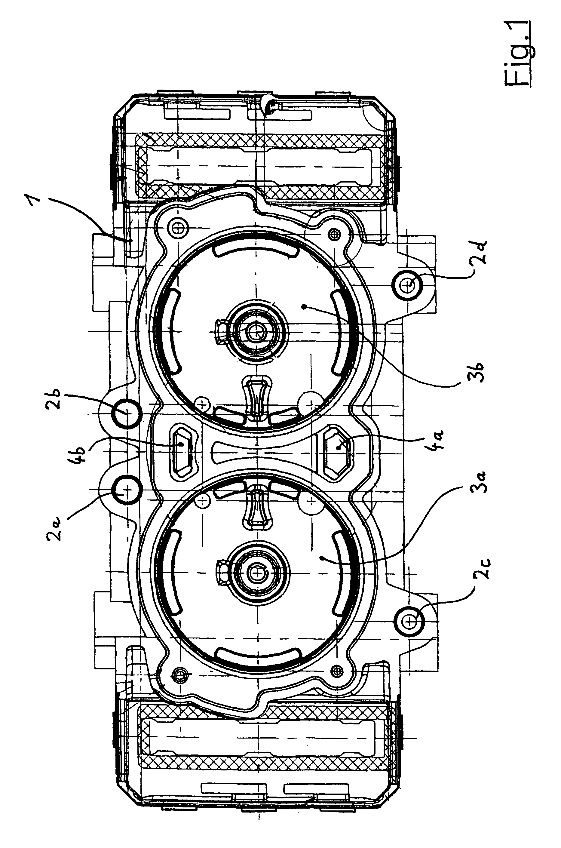
[0021]According to FIG. 1, an electropneumatic double regulating valve includes a relay valve housing 1, which is connected to a pilot valve housing (not illustrated here). The contact surface of the pilot valve housing is designed to correspond to the relay valve housing 1 along the line of a conventional half of the housing and is screwed by way of diverse boreholes 2a–2d to the relay valve housing 1. Inside the relay valve housing 1 there are two axis-parallel control chambers 3a, 3b, in which there are control pistons (also not shown here in detail) to actuate the valve along the line of a pre-controlled seat valve. The control piston is actuated by way of a pilot valve assembly, which is housed in the pilot valve housing, and which comprises individual, electrically switched solenoid valves. Between the two control chambers 3a and 3b there are two pressure medium channels 4a, 4b, which run between the relay valve housing 1 and the pilot valve housing and which serve to guide th...


PUM


Abstract

Electropneumatic double regulating valve for an air-operated vehicle brake system, which is disposed centrally on a wheel axle, equipped with two brakes, with a common relay valve housing (1), in which is integrated for each brake an assigned regulating valve unit, which comprises for valve actuation a control piston, which can be axially adjusted and is disposed inside an assigned control chamber (3a, 3b) and which is driven with a control pressure by way of an electromagnetic pilot valve assembly, housed in an adjacent pilot valve housing, for independent axial adjustment, whereby the pilot valve housing is connected detachably to the relay valve housing (1) by way of a sealing arrangement that lies in-between, whereby the sealing arrangement is designed as one-piece and comprises two sealing ring segments (5a, 5b), which are in essence ring-shaped and are assigned to one control chamber (3a, 3b) each and which are connected together by means of several footbridges (6a to 6c), which are molded on in-between and which are separated from each other in such a manner between the two sealing ring segments (5a, 5b) that an elastic deformation of the footbridges (6a to 6c) results in a defined compensation of the tolerance of the relative position of both sealing ring segments (5a, 5b) in the connecting plane between the pilot valve housing and the relay valve housing (1).

Description

[0001]The present application is an International Patent Application No. PCT / EP02 / 04628, filed Apr. 26, 2002, designating the United States of America and published in German as WO 02 / 102635, the entire disclosure of which is incorporated herein by reference. Priority is claimed based on Federal Republic of Germany Patent Application No. 101 20 324.1, filed Apr. 26, 2001.BACKGROUND AND SUMMARY OF THE INVENTION[0002]The invention relates to an electropneumatic double regulating valve for an air-operated vehicle brake system.[0003]The electropneumatic double regulating valve of the present invention is disposed centrally on a wheel axle, equipped with two brakes, with a common relay valve housing, in which is integrated for each brake an assigned regulating valve unit, which comprises for valve actuation a control piston, which can be axially adjusted and is disposed inside an assigned control chamber and which is driven with a control pressure by way of an electromagnetic pilot valve...

Claims


Application Information

Patent Timeline
IPC IPC(8): B60T13/68F16J15/06B60T1/00B60T15/02B60T15/18
CPCB60T15/027F16J15/061Y10T137/87209
Inventor ROETHER, FRIEDBERTDEJA, SIEGMUNDSCHAFFERT, EBERHARD
Owner KNORR-BREMSE SYST FUER NUTZFAHRZEUGE GMBH
Why Eureka
Try Eureka