
Non-invasive measurement of fluid-pressure diffusivity using electro-osmosis

a fluid-pressure diffusivity and electro-osmosis technology, applied in the field of well logging of earth boreholes, can solve the problems of inability to use continuous logging tools, inability to measure continuously the permeability of porous rock directly, and inability to easily cross the pressure barrier of mudcake, so as to facilitate the electrode injecting electrical curren

Active Publication Date: 2006-12-19
SCHLUMBERGER TECH CORP
View PDF20 Cites 3 Cited by
  • Summary
  • Abstract
  • Description
  • Claims
  • Application Information

AI Technical Summary

Benefits of technology

This approach allows for rapid, non-invasive, and continuous measurement of fluid-pressure diffusivity, enabling accurate permeability assessment of porous rock formations from a downhole tool, facilitating better reservoir evaluation and fluid production rates.

Problems solved by technology

These methods are unable to measure continuously the permeability of porous rock directly with accuracy from a downhole tool.
Streaming potential measurements cannot cross easily the mudcake pressure barrier and cannot be used as a continuous logging tool as it needs to impose a big differential pressure and requires time for the pressure front to diffuse into the formation.
Electro-osmotic measurements are closely related to permeability see (U.S. Pat. No. 5,417,104); however, measuring the induced pressure field through the mudcake with a pressure gauge is not feasible because the mudcake is a pressure barrier.

Method used


Image

  • Non-invasive measurement of fluid-pressure diffusivity using electro-osmosis
  • Non-invasive measurement of fluid-pressure diffusivity using electro-osmosis
  • Non-invasive measurement of fluid-pressure diffusivity using electro-osmosis

Examples


Embodiment Construction

[0025]The present invention will be described in detail with reference to the drawings.

[0026]Like reference numerals are used to denote like items throughout the various figures.

[0027]The invention relates generally to well logging of Earth boreholes and, more particularly, to a method and apparatus for determining the properties of subsurface rock such as diffusivity of porous media.

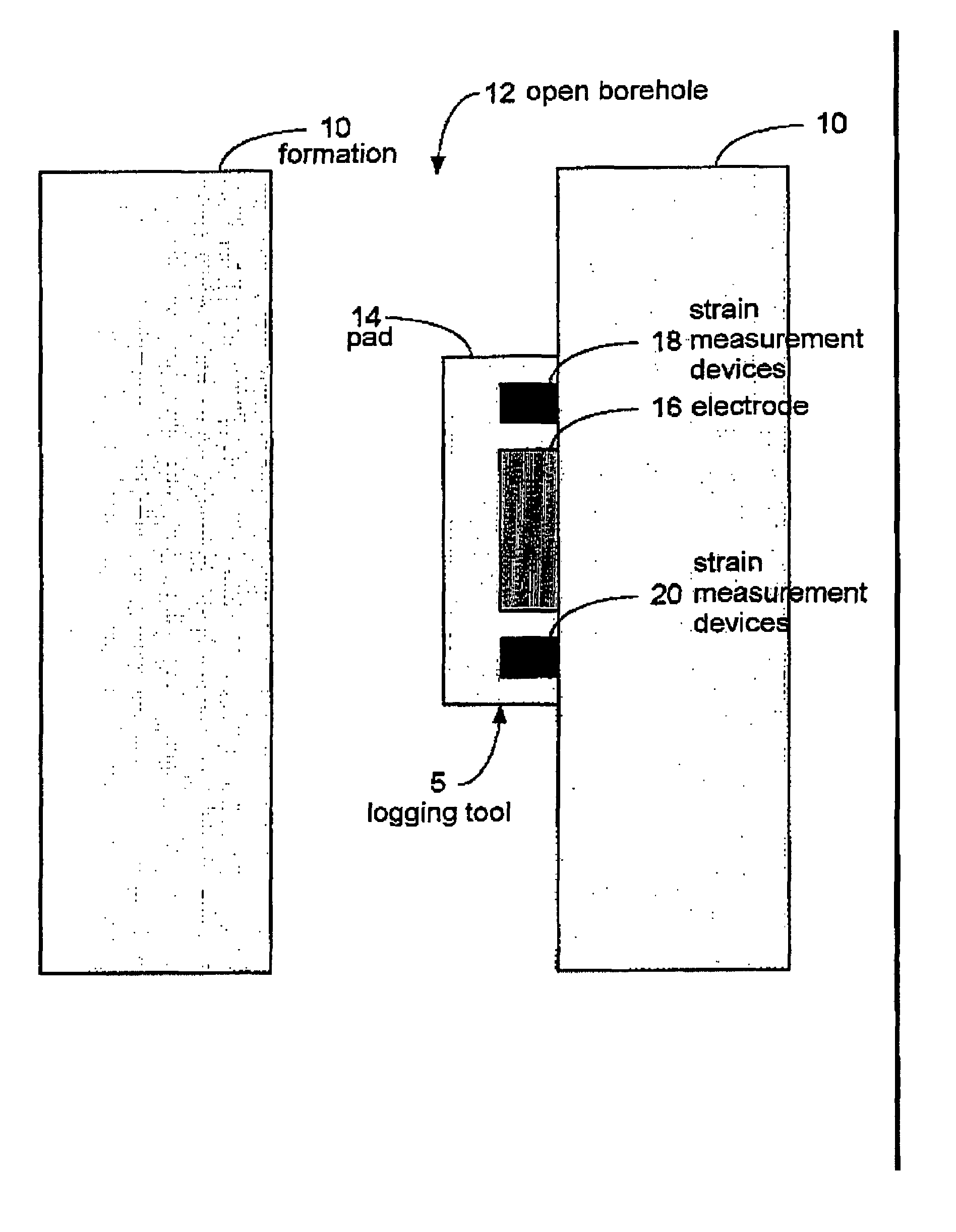
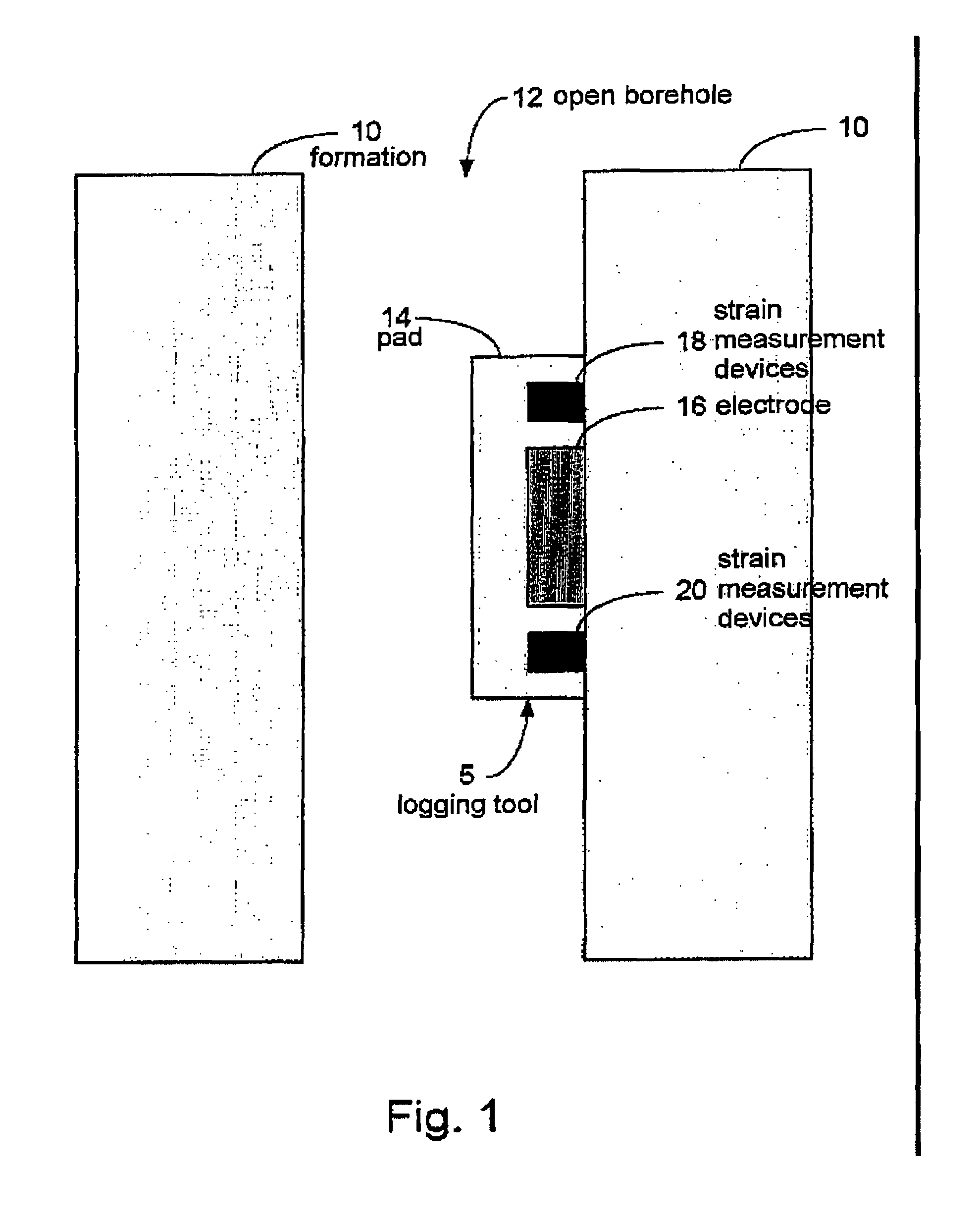
[0028]Referring to FIG. 1, a logging tool (5) for making electro-osmotic measurements in a formation (10) in an open borehole (12) is shown. In one or more embodiments, the logging tool (5) includes a pad (14), which is capable of being mounted against the wall of the borehole (12). The pad (14) includes an electrode (16) and strain measurement devices (18),(20). The electrode (16) is capable of injecting electrical current into the borehole wall. The strain measurement devices (18),(20) are capable of measuring the displacement, or the strain, with respect to time. Those skilled in the art will appreci...


PUM


Abstract

An apparatus for determining fluid-pressure diffusivity in a borehole (12) in a formation (10) includes an electrode (16) and a strain measuring device (18),(20) (or a particle velocity measuring device (18),(20) or a particle acceleration measuring device (18),(20)) disposed a fixed distance from the electrode (16). The electrode (16) injects an electrical current into a point on a wall of the borehole (12). The strain measuring device (18),(20) measures strain (or the particle velocity measuring device (18),(20) measuresd particle velocity or the particle acceleration measuring device (18),(20) measures particle acceleration) at the fixed distance from the point of injection of the electrical current over time. The fluid-pressure diffusivity is determined based on the measured strain (or measured particle velocity or measured particle acceleration) over time. A method of determining a fluid-pressure diffusivity in a borehole (12) includes injecting an electrical current into a point on a wall of the borehole (12), measuring at least one of strain, particle velocity, and particle acceleration at a fixed distance from the point of injection of the electrical current over time, and determining the fluid-pressure diffusivity based on the measured at least one of strain, particle velocity, and particle acceleration over time.

Description

BACKGROUND OF INVENTION[0001]1. Field of the Invention[0002]The invention relates generally to well logging of Earth boreholes and, more particularly, to a method and apparatus for determining the properties of subsurface rock such as fluid-pressure diffusivity of porous media.[0003]2. Background Art[0004]U.S. Pat. No. 3,599,085 describes a method in which a sonic source is lowered down a borehole and used to emit low frequency sound waves. Electrokinetic effects in the surrounding fluid-bearing rock cause an oscillating electric field in this and is measured at least two locations close to the source by contact pad touching the borehole wall. The ratio of the measured potentials being related to the electrokinetic skin depth to provide an indication of permeability of the formation.[0005]U.S. Pat. No. 4,427,944 describes a method which injects fluid at high pressure of alternating polarity to the formation and measurement of the generated transient streaming potentials in the time ...

Claims


Application Information

Patent Timeline
Patent Type & Authority Patents(United States)
IPC IPC(8): E21B47/06G01V3/02
CPCG01V3/24G01N2015/1075G01N2015/1027
Inventor CHARARA, MARWANPRIDE, STEVENLIGNEUL, PATRICE
Owner SCHLUMBERGER TECH CORP
Learn More