Detection of background toner particles

Inactive Publication Date: 2006-12-12
EASTMAN KODAK CO
View PDF11 Cites 2 Cited by
  • Summary
  • Abstract
  • Description
  • Claims
  • Application Information

AI Technical Summary

Benefits of technology

[0028]In one embodiment, a test area latent image on a moving photoconductor surface is created in the form of alternating strips such that toning at a background level is prevented in one set of strips, and allowed in the other set of strips. The strips are aligned perpendicular to the direction of motion of the photoconductor. After development, the pattern of toned strips passing under a small aperture detector such as for example a bar code reader results in an easily detectable AC signal.
[0032]In still yet another preferred embodiment, a test area latent image on an imaging member includes strips, which repel well-charged toner particles under the applied conditions in the development station, and these strips alternate with strips of a different charge density, which also repel well-charged toner particles. The inhomogeneous electric fields acting between the alternating strips external to the imaging member produce polarization forces on uncharged toner particles, or on particles having a very low charge. These short-range polarization forces can cause nearby uncharged or low charged toner particles to be attracted to the surface of the imaging member, resulting in a set of toned strips having double the frequency of the test area latent image. The configuration of this embodiment amplifies the difference between no toning and low charge toning so as to make the reflectance change larger and thus readily detectable by an installed wide aperture densitometer.

Problems solved by technology

Under most conditions it is impractical to measure such a background coverage directly.

Method used


Image

  • Detection of background toner particles
  • Detection of background toner particles
  • Detection of background toner particles

Examples


embodiment 100

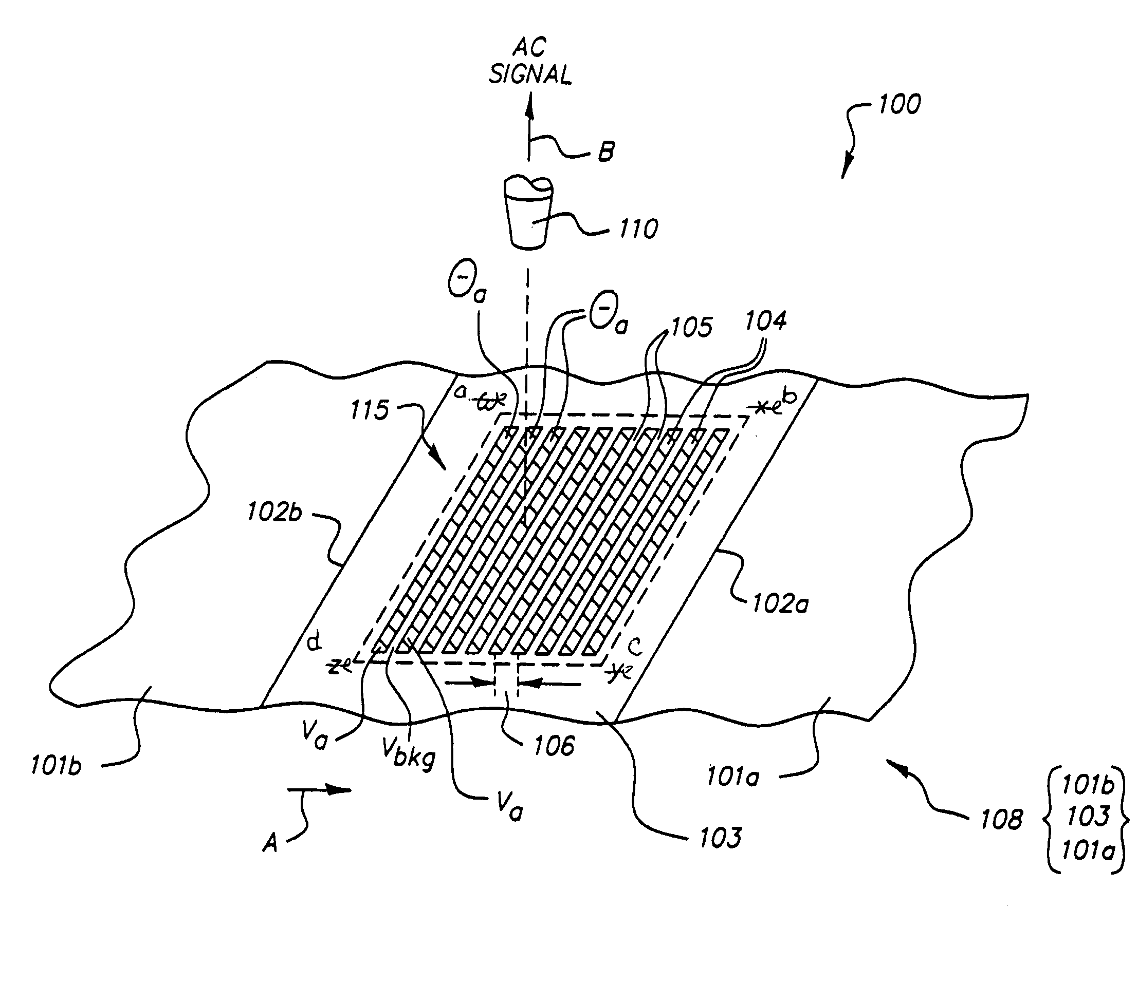
[0056]Returning to embodiment 100, strips 104 may, depending on developer age, include toner particles representative of toner particles in a background portion of a toner image in an image frame 101a,b. The spaces 105 are substantially free of toner particles. It is preferred that strips 104 and spaces 105 all have a width of approximately 0.5 mm, such that the width of a distance 106 between each pair of like strips 104 is about 1 mm. However, any suitable widths for strips 104 and spaces 105 may be employed.

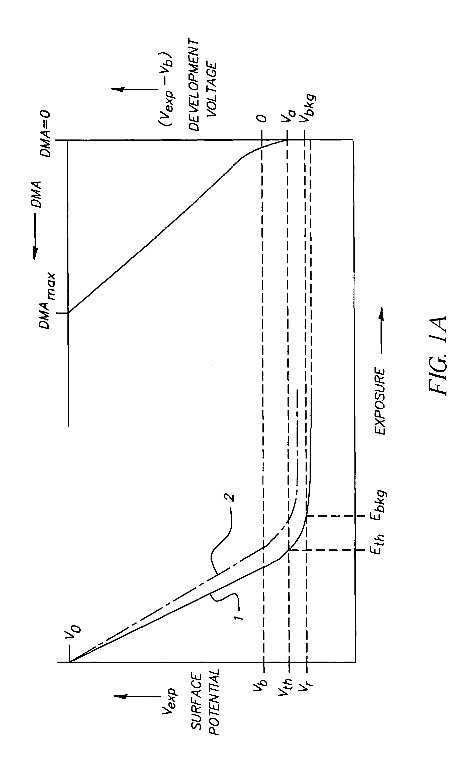
[0057]Referring again to the exemplary FIGS. 1A, 1B (as well as FIG. 2), spaces 105 are substantially free of toner (e.g., originated on a photoconductor by a photoexposure producing a development voltage preferably of magnitude less than or equal to the background development voltage, for example Vbkg). The strips 104 have a toner coverage θa, with θa originating in relation to a threshold development voltage, e.g., the threshold development voltage Va in FIG. 1A. As explaine...

embodiment 200

[0069]In another preferred embodiment (not illustrated) synchronous detection is used in a manner analogous to the manner of embodiment 200, except that the reference AC signal is not obtained from a parallel patch but is derived from other sources permitting good synchronization with the strips in the control patch area. These other sources, which are preferably of non-electrostatographic origin, include encoder signals accurately monitoring the position of the toner-image-bearing member, perforations located along an edge of a toner-image-bearing member in the form of a web or belt, or image registration marks located on the toner-image-bearing member. Thus when the control AC signal has a certain frequency, the reference AC signal preferably has a calibrated amplitude and a reference frequency suitable for use with the control AC signal in a synchronous detection circuit, so that the synchronous detection circuit produces a DC output having an amplitude proportional to the low co...

embodiment 300

[0070]In a preferred embodiment 300 illustrated in FIG. 4, a low coverage of toner particles relating to a background area of a toner image in an image frame is included in a composite toner patch image 315 located on a toner-image-bearing member 325 (member 325 partially indicated, image frame not indicated in FIG. 4). Preferably, the toner-image-bearing member 325 is a photoconductive imaging member. The composite toner patch image 315, defined by the parallelogram, efgh, is located in a non-image area which is preferably an interframe area, the composite toner patch image 315 including a plurality of equally spaced toned strips inclusive of strips 304 and 306. Strips 304 and 306 are mutually parallel and perpendicular to the direction of movement of toner-image-bearing member 325, as indicated by the arrow, A″.

[0071]The toned strips include control toned strips 304 and reference-toned strips 306, the control toned strips 304 having a lower coverage of toner than the reference-ton...


PUM


Abstract

Apparatus and method to detect and measure, in a non-image area on a toner-image-bearing member, a low coverage of toner particles relating to a background coverage of toner particles in an image frame, and in particular, to detect and measure by an optical detector a low toner coverage in excess of a threshold coverage or a pre-selected coverage and thereby produce a signal, e.g., a process control signal. Such a process control signal can be used to adjust the operating parameters of a process in a subsystem, such as a toning process or a photoexposure process. In preferred embodiments, synchronous detection is used to extract a signal having a magnitude proportional to the low toner coverage representative of the background coverage of toner particles.

Description

CROSS REFERENCE TO RELATED APPLICATION [0001]Reference is made to and priority claimed from U.S. Provisional Application Ser. No. 60 / 477,481, filed Jun. 10, 2003, entitled DETECTION OF BACKGROUND TONER PARTILCES.FIELD OF THE INVENTION[0002]The invention relates to electrostatography and to an apparatus and method to detect a low coverage of toner particles on a toner-image-bearing member, and in particular to detect or monitor background toner having a low coverage in excess of a threshold coverage and thereby produce a signal.BACKGROUND OF THE INVENTION[0003]An exemplary modular color printer includes a number of tandemly arranged electrophotographic image-forming modules (see for example, U.S. Pat. No. 6,184,911). Such a printer includes two or more single-color image forming stations or modules arranged in tandem and an insulating transport web for moving receiver members such as paper sheets through the image forming stations, wherein in each module a single-color toner image is...

Claims


Application Information

Patent Timeline
IPC IPC(8): G03G15/00
CPCG03G15/5058
Inventor BARES, JAN
Owner EASTMAN KODAK CO
Why Eureka
Try Eureka