
Coaxial quick disconnect coupling

a technology of quick disconnect and coaxial coupling, which is applied in the direction of water installations, thin material handling, construction, etc., can solve the problems of difficult connection of the two halves, harmful to the coaxial coupling assembly, so as to relieve any residual pressure buildup

Active Publication Date: 2006-12-12
PARKER INTANGIBLES LLC
View PDF9 Cites 21 Cited by
  • Summary
  • Abstract
  • Description
  • Claims
  • Application Information

AI Technical Summary

Benefits of technology

[0016]Still another feature of the present invention includes providing a method of operatively, fluidly and concentrically interconnecting adjoining proximate ends of self-contained subassemblies comprised of first and second coaxial coupling halves, with the distal end of each of said coupling halves being operatively, fluidly interconnected with a separate hose assembly. The hose assembly includes a flexible hose assembly having multiple conduits, each of said conduits being, in turn, connected with an individual hose fitting. The coupling halves, together with their respective hose assemblies form a coupling assembly between a driving member and a driven member. The noted method initially maintains an operative fluid connection between the concentric inner and outer passages of the first coupling half, which are connected via separate conduits and hose fittings to the driving member, while concurrently isolating concentric inner and outer passages of the second coupling half, which are connected via further separate conduits and hose fittings to the driven member. The method then fluidly connects one of the second coaxial coupling member inner and outer passages with one of the first coaxial coupling member inner and outer passages in order to relieve any residual pressure buildup in the second coaxial coupling member. The method finally fluidly interconnects the first and second coaxial coupling member inner passages and the first and second coaxial coupling member outer passages, thereby empowering the driven member.

Problems solved by technology

Trapped pressurized fluid or flow impediments are harmful to the coaxial coupling assembly.
Connection of the two halves is difficult if the pressure in either half has escalated due to trapped fluid.
Sudden pressure surges within the hose assemblies can cause harm to all of the components.
In addition, sudden pressure spikes within the assembly can extrude the seals that reside in and between the components.
It is cost prohibitive to replace both the conduit and its mating coaxial coupling.
Therefore, replacement of the hose assembly, which is comprised of the conduit and attached end fitting, is impractical without replacing the coupling.
Small passageways restrict the fluid flow and interrupt the smooth continuous passage of fluid.
Since it is costly and inconvenient to carry both styles of mating coaxial couplings, it is desirable to have but one coaxial coupling that can mate with both the twin line and coaxial styled conduits.
If contaminants do enter, the joints and seals of the mating componentry can be adversely affected.
Soft connecting joints between the components can allow one component to move radially relative to another, thus causing this coupling half to be eccentric.
Although this design reduces the number of components for the entire coaxial coupling assembly, i.e. the coaxial coupler with the hose assembly, it also eliminates any reusability of the coaxial coupling.
The entire coaxial coupling assembly has to be replaced in such a case, which adds cost for the enduser.

Method used


Image

  • Coaxial quick disconnect coupling
  • Coaxial quick disconnect coupling
  • Coaxial quick disconnect coupling

Examples


Embodiment Construction

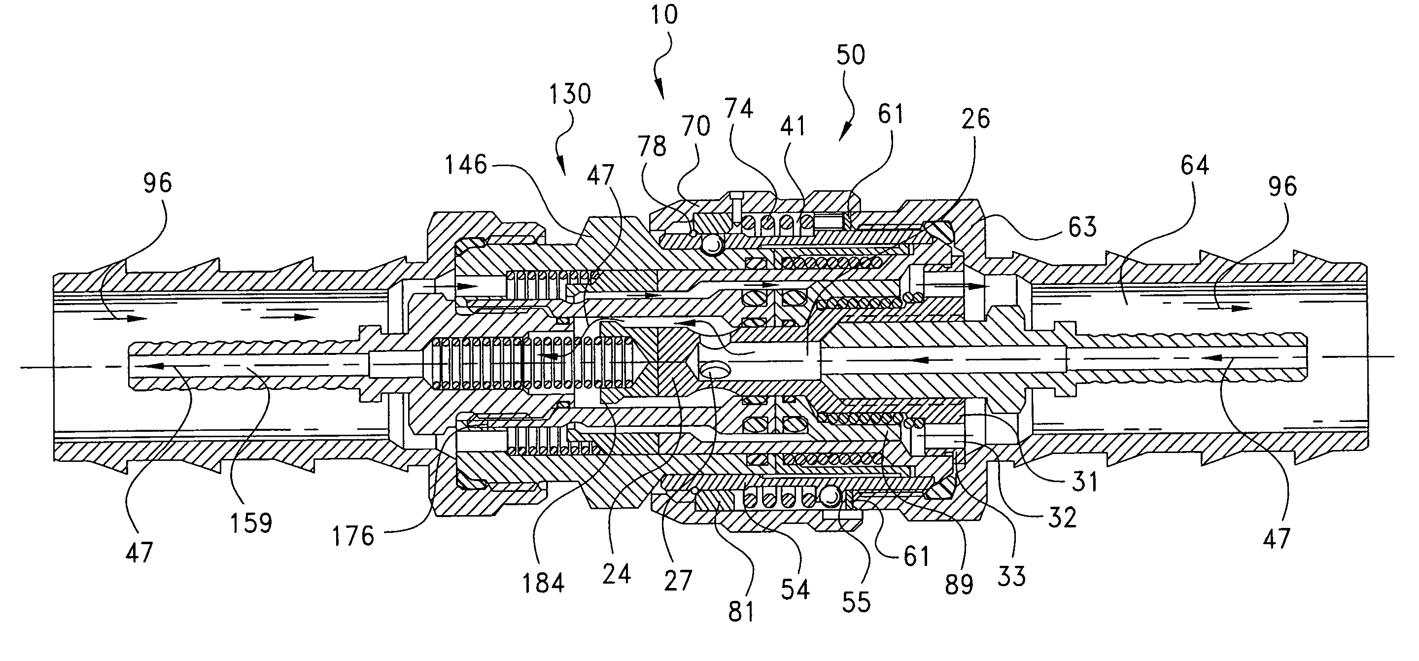
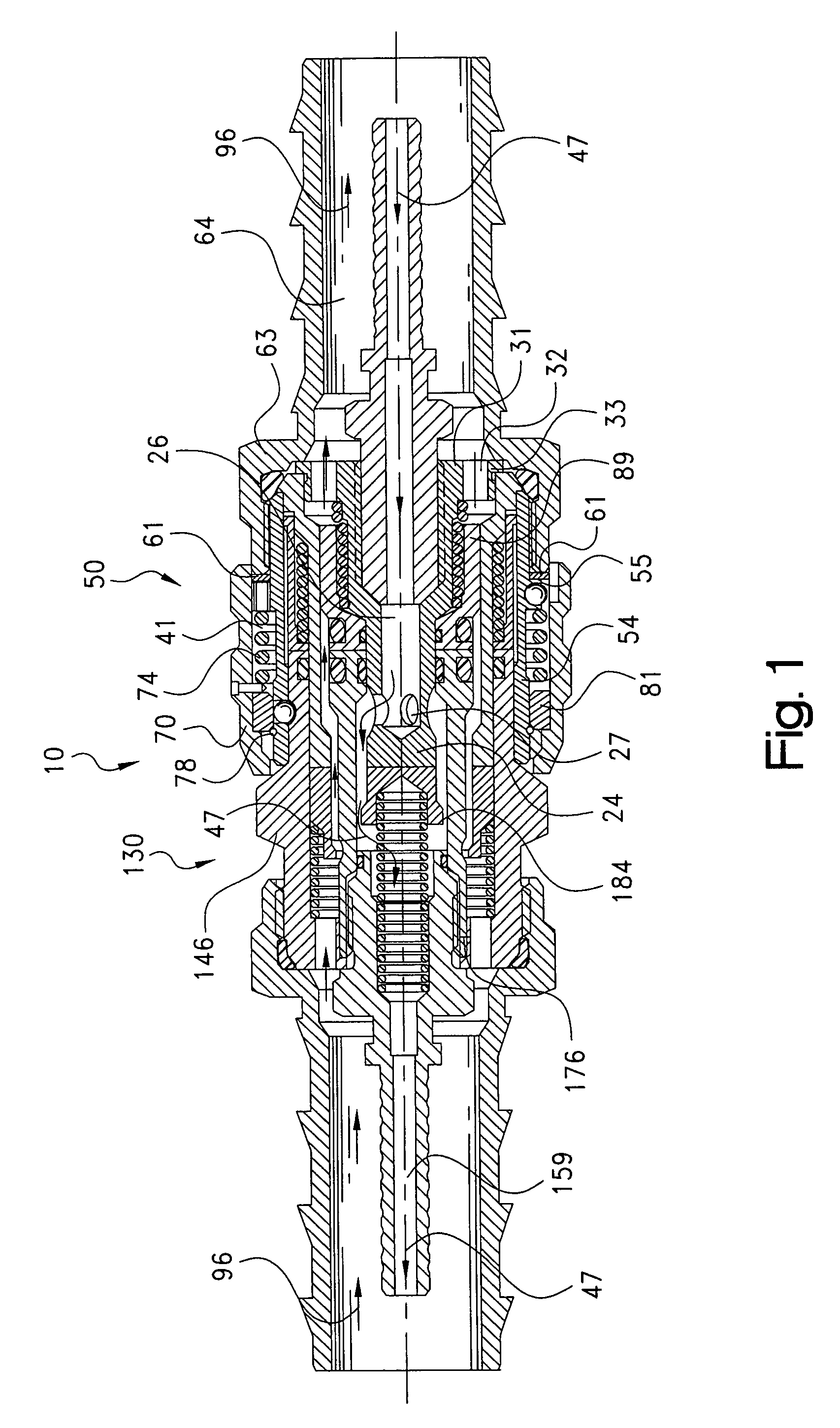
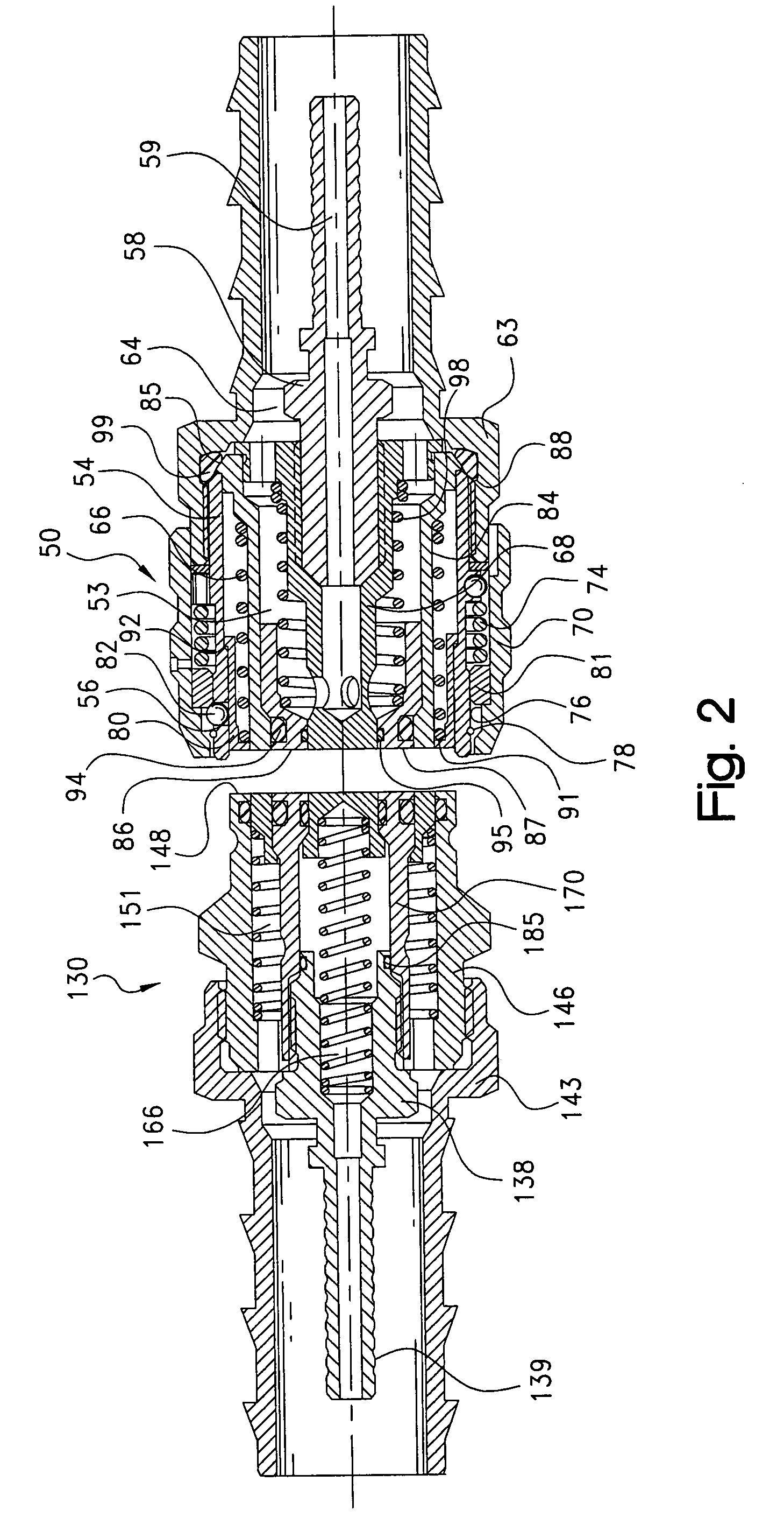
[0035]Referring to FIG. 1, the present invention relates to a first embodiment 10 of a coaxial coupling that is utilized for quickly connecting and disconnecting coaxial hoses or twin line hose assemblies. Coaxial coupling 10, when connected with hose assemblies, can be particularly useful for connecting a piece of construction or industrial equipment (e.g. pump) to a remote implement (e.g. a piece of rescue equipment), however, it should be appreciated that such couplings could be used for a variety of applications that require quick connection and disconnection. Coaxial coupling 10 enables the system to have just one coupling and one coaxial hose instead of two separate hoses and couplings. The present invention is more compact, lightweight and easier for an end user to connect and use. Other applications include any system that utilizes two hoses which can be combined into one hose for the noted reasons.

[0036]Referring to FIGS. 1, 2 and 4, coaxial coupling 10 is comprised of a ma...


PUM


Abstract

A quick disconnect coupler apparatus fluidly connecting coaxially aligned first and second couplings (50, 130), wherein the both couplings (50, 130) have an inner high pressure passage (26) and a coaxial outer lower pressure passage (53). Initially the first coupling inner high pressure passage (26) is fluidly connected with the first outer lower pressure passage (53) while isolating the second coupling inner high pressure passage (166) and the coaxial outer lower pressure passage (151). Then the first coupling inner high pressure passage (26) and one of the second coupling inner and outer passages (166, 151) is fluidly connected with the first coupling coaxial outer lower pressure passage (53) while isolating the other of the second coupling inner and outer passages (166, 151). Finally the first coupling inner high pressure passage (26) is fluidly connected with the second coupling inner high pressure passage (166) and the first coupling coaxial outer lower pressure passage (53) is fluidly connected with the second coupling coaxial outer lower pressure passage (151).

Description

CROSS-REFERENCE TO RELATED CASES[0001]The present application claims the benefit of the filing date of U.S. Provisional Application Ser. No. 60 / 475,289 filed Jun. 3, 2003, and U.S. Provisional Application Ser. No. 60 / 491,657 filed Jul. 29, 2003, the disclosure of which is expressly incorporated herein by reference.FIELD OF THE INVENTION[0002]The present invention relates to quick disconnect, concentric coaxial couplings and their attachment with mating hose assemblies.BACKGROUND OF THE INVENTION[0003]Coaxial couplings, particularly those which conduct high and low pressure fluids, are well known in the art. An example of such a coupling is shown in U.S. Pat. No. 6,179,001 B1 to Schutz. This type of coupling assembly permits a rapid-action connection of a male and female coupling that sealingly closes when the male and female halves are disconnected. Typically, these concentric, coaxial coupling are attached with coaxial hose assemblies.[0004]Coaxial hose assemblies are generally use...

Claims


Application Information

Patent Timeline
Patent Type & Authority Patents(United States)
IPC IPC(8): F16L37/34F16L37/56
CPCF16L37/34F16L37/35F16L37/565Y10T137/0491Y10T137/87949Y10T137/87957
Inventor MALDAVS, OJARS
Owner PARKER INTANGIBLES LLC
Learn More