
Vascular clamp

a technology of microvascular clamps and clamps, which is applied in the field of microvascular clamps, can solve the problems of permanent occlusion or traumatic damage of the vessel, damage to the vessel, pinching and crushing effect of the vessel, etc., and achieves the effect of optimizing the occlusion of the vessel, minimizing the trauma to the vessel, and uniform closing for

Active Publication Date: 2006-12-05
SYNOVIS LIFE TECH
View PDF23 Cites 270 Cited by
  • Summary
  • Abstract
  • Description
  • Claims
  • Application Information

AI Technical Summary

Benefits of technology

[0018]The present invention provides a vascular clamp for temporarily occluding a blood vessel so that when the jaws of the clamp are placed around a vessel, the closing forces are uniformly distributed along the length of the jaws and over the diameter of the vessel. Because the present clamp imparts a uniform closing force, vessel occlusion is optimized and trauma to the vessel is minimized.
[0020]The jaws of the present invention will be described in terms of “opened”, “closed”, and “lifted” positions. The ability of the jaws to assume the lifted position is what enables the present clamp to impart uniform closing forces along the length of the jaws and over the diameter of a blood vessel. The pivoting point of the present invention provides for this lifting ability. When the jaws are in an opened position, the contact surfaces of the jaws are separated from one another but are not substantially parallel to one another. When the jaws are in a closed position, the contact surfaces are in contact with one another and are also substantially parallel to one another. When the jaws are in a lifted position, the contact surfaces are slightly spaced from one another and are also substantially parallel to one another. The lifted position can be thought of as a variation of the closed position where the contact surfaces are slightly spaced rather than contacting one another. Typically, when the present clamp is left alone in it's natural state, the jaws are maintained in a closed position. When force is applied to the clamp handles, the jaws assume an open position. When the clamp is positioned about a blood vessel and the force is released from the handles, the rigidity of the walls of the collapsed blood vessel causes the jaws to assume a lifted position.

Problems solved by technology

One problem associated with biased clamps is that the closing force exhibited by the jaws may cause damage to the vessel.
For example, the closing force may be too strong for the particular vessel used, so that the jaws exhibit a pinching and crushing effect on the vessel.
Also, when the jaws of most clamps are in a closed position about a blood vessel, the contact surfaces of the jaws are not maintained in a parallel relationship along the length of the jaws.
In either case, these overly strong or uneven closing forces may result in permanent occlusion of, or traumatic damage to, the vessel.
While these adjustable clamps provide certain advantages, they are often more difficult to use during surgery than the biased clamps.
It is time consuming and cumbersome for a surgeon to have to adjust the closing force, particularly during the wet and slippery conditions of surgery.
Adjustable clamps also tend to be more susceptible to operator error than the biased clamps which have a preset closing force.

Method used


Image

  • Vascular clamp
  • Vascular clamp
  • Vascular clamp

Examples


Embodiment Construction

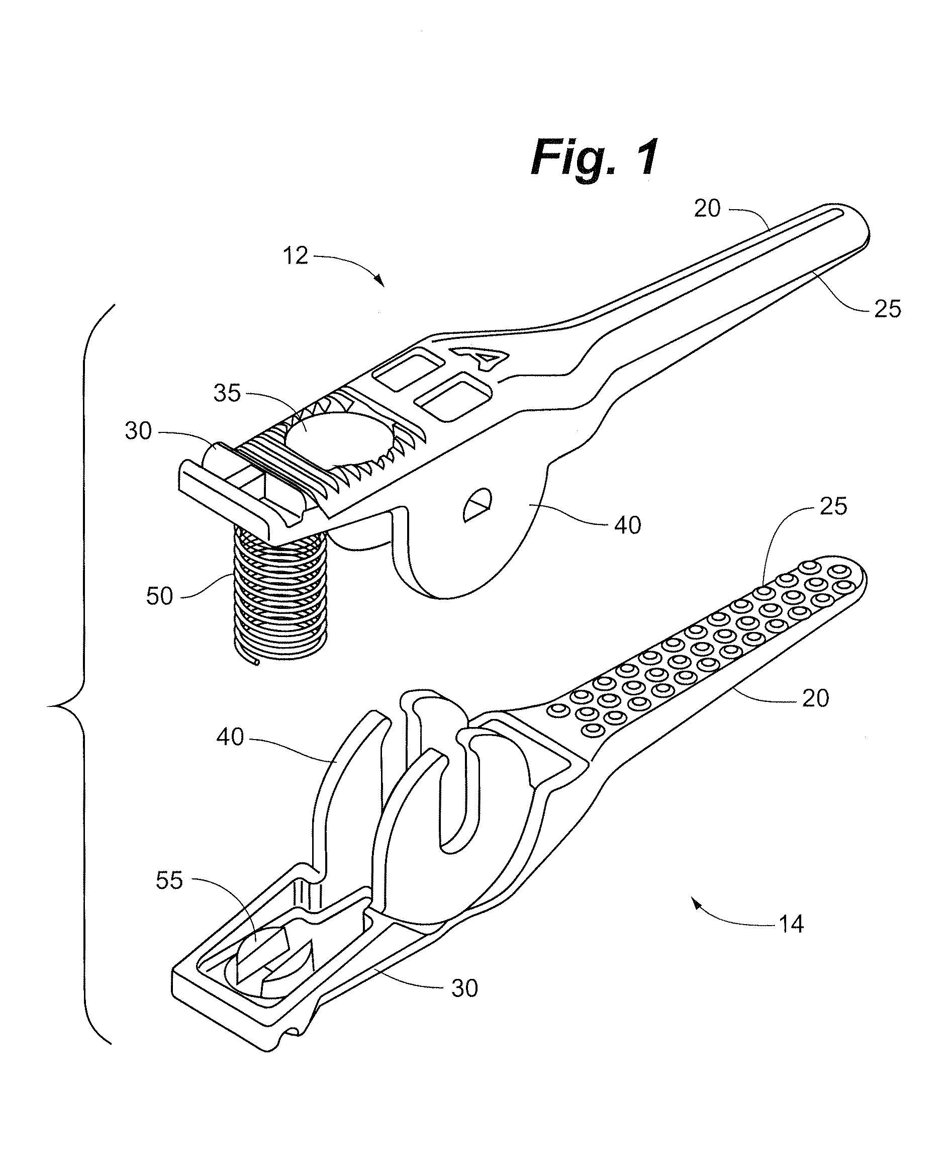
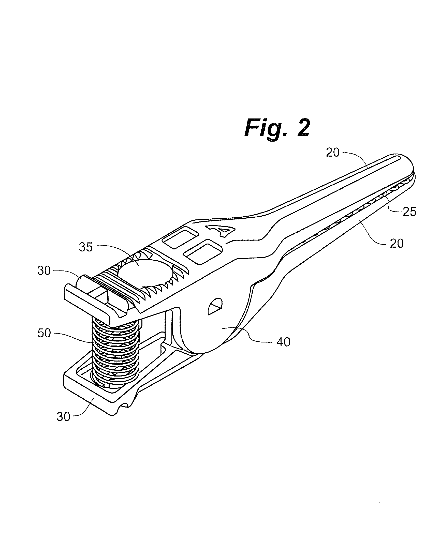
[0023]With reference to the FIGS. 1–9, the preferred embodiments of the vascular clamp will now be described.

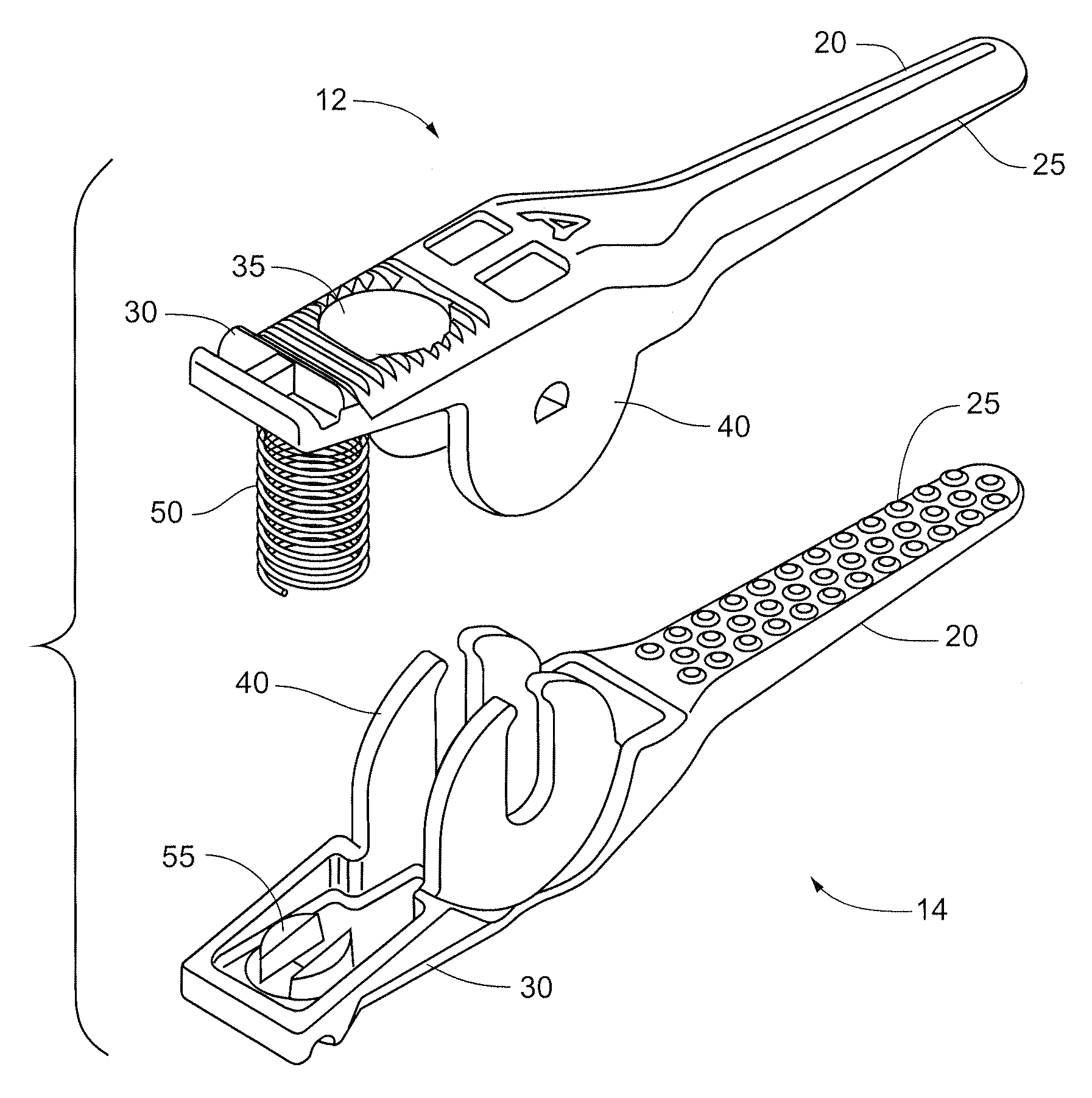
[0024]The preferred vascular clamp includes two clamp members, 12 and 14. Each clamp member includes a handle 30, a pivoting point 40 and a jaw 20. FIGS. 1 and 3 show the clamp members in an unconnected form. FIGS. 2 and 4 show the clamp members in a connected form. The clamp members are connected together at their pivoting point 40.

[0025]The handles are adapted to be held by forceps or by hand (for example by fitting a user's thumb and forefinger). Each handle 30 also includes a handle surface 35. In some embodiments, the handle surface 35 is formed as a non-slip surface. The non-slip surface can have any suitable configuration to prevent slippage. For example, the surface can include grooves or ribs or the surface can be sandblasted to form a rougher surface having better gripping. The non-slip surface also makes it easier to grasp the handles during the slippery conditions...


PUM


Abstract

A vascular clamp and a method for temporarily occluding a vessel. The vascular clamp comprises two jaws, two handles, and a pivoting point. A biasing mechanism is positioned between the handles for biasing the handles apart so that a closing force is imparted along the length of the jaws. The pivoting points pivotally connect the jaws together and are also configured to allow one jaw to be lifted relative to the other jaw. The method of temporarily occluding a blood vessel comprises the steps of providing a vascular clamp as described above and positioning the clamp about a blood vessel.

Description

FIELD OF THE INVENTION[0001]The present invention relates generally to vascular clamps. More specifically, the present invention relates to microvascular clamps for the temporary occlusion of small blood vessels.BACKGROUND OF THE INVENTION[0002]Over the years, several different devices have been developed to temporarily occlude blood vessels during surgery. These devices are widely varied and include many different configurations. Clamps have become an increasingly popular device of choice and a wide variety of clamp types have been developed for use in vascular surgery.[0003]Clamps are available in both large and small sizes. Larger clamps typically have large shafts or handles and are most suitable for occluding larger blood vessels in surgery procedures where sufficient space is available at the surgical site. Small surgical clamps are ideal for use with smaller vessels in microvascular surgery where little space is provided.[0004]Popular small clamps include “bulldog” clamps. “B...

Claims


Application Information

Patent Timeline
IPC IPC(8): A61B17/22A61B17/08A61B17/12A61B17/122A61L
CPCA61B17/12A61B17/1227A61B2019/444A61B90/92
Inventor KUESTER, III, WILLIAM FRANK
Owner SYNOVIS LIFE TECH
Learn More