Door hinge pin removal tool

a tool and hinge pin technology, applied in the field of multifunctional hand tools, can solve the problems of affecting the use of the tool, so as to reduce the tendency of users, reduce the chance that the tool will skip off the hinge pin and damage the surrounding woodwork

Inactive Publication Date: 2006-12-05
WOOD SAMUEL T
View PDF21 Cites 18 Cited by
  • Summary
  • Abstract
  • Description
  • Claims
  • Application Information

AI Technical Summary

Benefits of technology

[0005]The current invention has multiple advantages over the pliers-and-screwdriver process described above. The most apparent advantage is that the invention allows a user to remove a door hinge pin with two tools; namely, a hammer and the tool of the invention. The elongated design of the invention allows a user to reach tight corner areas and decreases the tendency of a user to angle the head portion of the tool during the hinge removal process, which decreases the chance that the tool will skip off the hinge pin and damage the surrounding woodwork. Additionally, the pry-bar design of the tool allows a user to fully extract the pintle or hinge pin once it has been broken free from the hinge plates. Similarly, during the door installation process, the bit portion of the current invention allows a user to align the holes in the separate hinge knuckles before the door is lifted in position and the pin is inserted. This allows the user to confirm that the hinge pin will slide all the way into both hinges before the door is moved into place.

Problems solved by technology

Also, the head of the screwdriver may be damaged so that it is no longer usable to drive screws.
Additionally the use of a screwdriver can also result in damaged woodwork if the head of the screwdriver skips off the hinge pin during the hinge removal process.
Additionally, due the awkward angle at which the screwdriver is held, the user may strike his or her hand with the hammer when attempting to strike the screwdriver.
However, these tool are generally overly complex and therefore more expensive to produce than the current invention, or overly simple and consequently less versatile than the current invention.

Method used


Image

  • Door hinge pin removal tool
  • Door hinge pin removal tool
  • Door hinge pin removal tool

Examples


Embodiment Construction

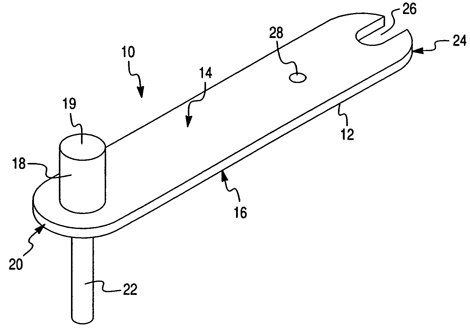
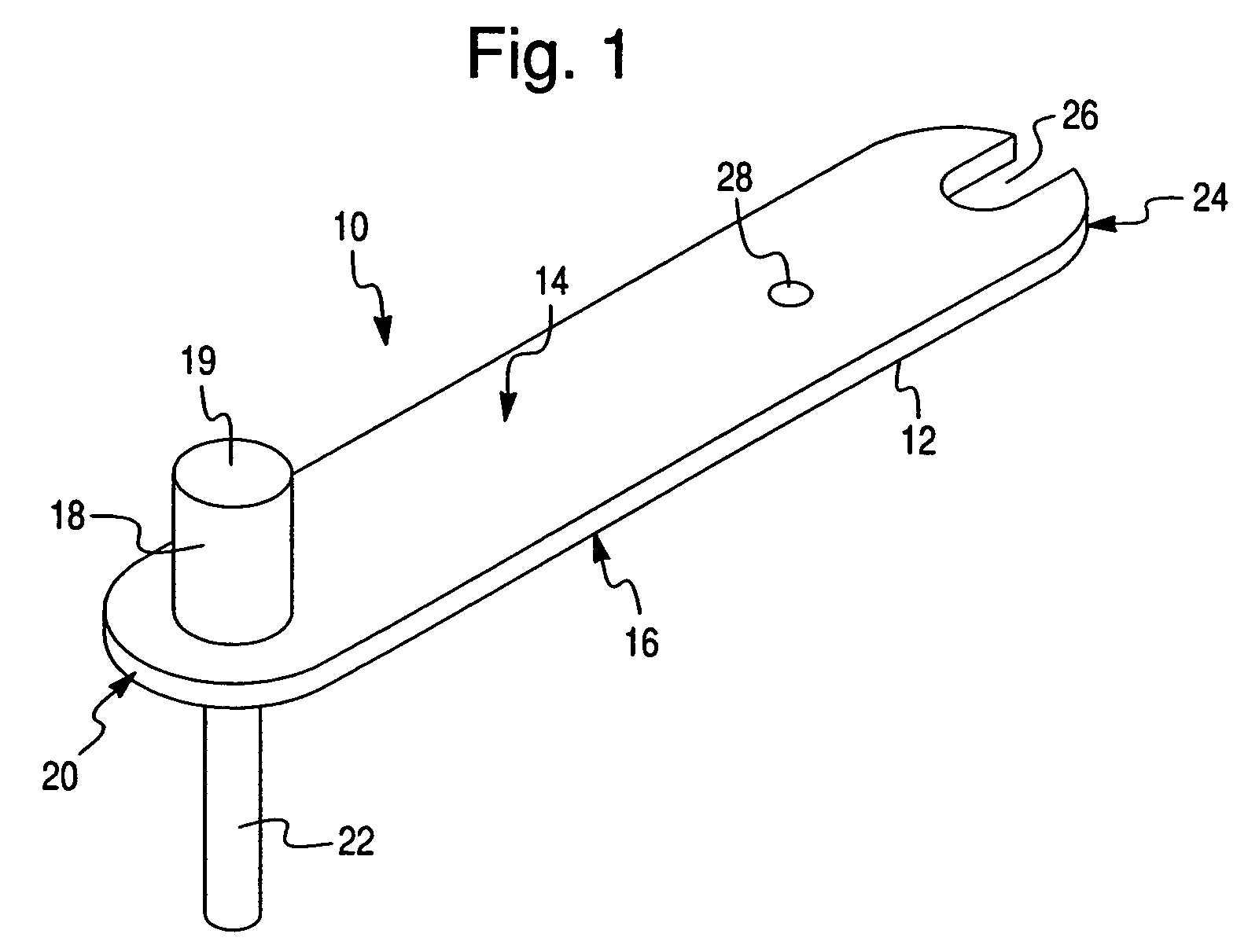
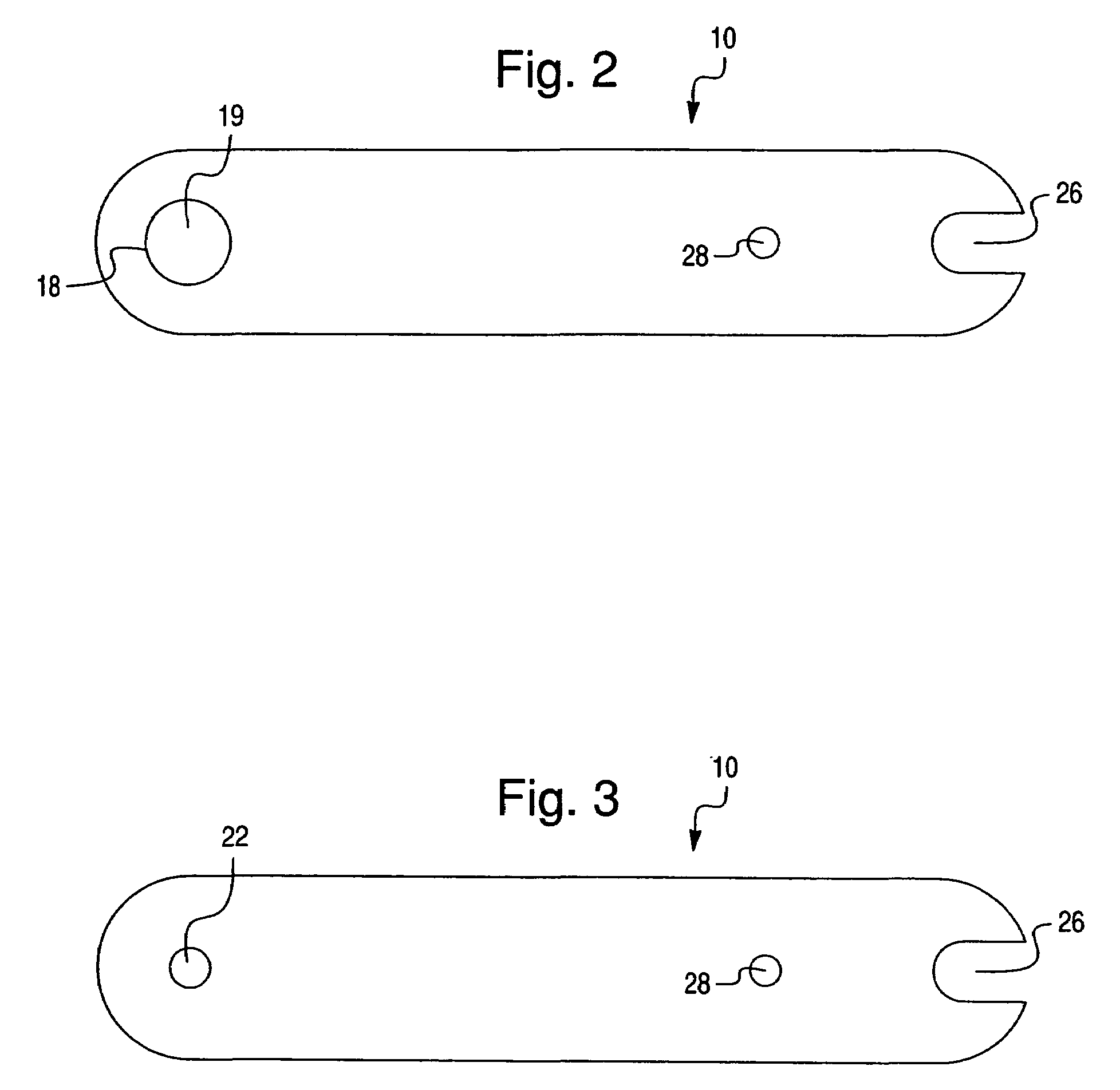
[0022]As best shown in FIGS. 1–7, a first embodiment of the invention comprises a tool 10 with an elongated body 12 having planar upper 14 and lower 16 sides. An elongated cylindrical anvil 18 with a planar striking surface 19 extends from the upper side 14 of tool 10 adjacent to first end 20 of the tool 10. A hinge pin bit 22 extends from the lower side 16 of the tool 10. Preferably, the anvil 18 is coaxially aligned with the bit 22, although it is merely necessary that the anvil 18 and hinge pin bit 22 extend in parallel in order to effect efficient transfer of force applied to anvil 18. The second end 24 of the tool 10 includes a hinge pin extractor slot 26 and a utility aperture 28. The slot 26 may be used to pry out and remove a pintle or hinge pin once the hinge pin bit 22 dislodges the hinge pin from the hinge. The utility aperture 28 can be used to suspend the tool 10 from a support, or as a connection point for a belt clip or carrying lanyard. Ends 24 and 20 are rounded in ...


PUM

PropertyMeasurementUnit
forceaaaaaaaaaa
diameteraaaaaaaaaa
elongate shapeaaaaaaaaaa

Abstract

A multifunction tool that allows a user to remove hinge pins and adjust hinges during the installation and removal of hinged doors. In the preferred embodiment, the tool has a hinge pin bit and an anvil extending perpendicularly from opposite sides of the first end of the tool. The second end of the tool includes a slot extending along the tool's centerline. In an alternate embodiment, the tool incorporates an anvil extending from each side of the tool, and a hinge pin bit extending from each side of the tool. The hinge pin bits have different sizes so that the tool can be used on door hinges with different size hinge pins.

Description

FIELD OF THE INVENTION[0001]The invention relates to a multi-function hand tool used during the installation and removal of hinged doors in order to remove the pintle from a door hinge.BACKGROUND OF THE INVENTION[0002]Many different techniques and tools may be used for removing door hinge pins. The most common method involves using the head of a screwdriver to force the hinge pin upwardly, and a pair of pliers to grasp the head of the pin and extract the pin from the knuckle elements of the door hinge. While this method is simple, it requires at least three separate tools; namely, a hammer, a screwdriver and pliers. Also, the head of the screwdriver may be damaged so that it is no longer usable to drive screws. Additionally the use of a screwdriver can also result in damaged woodwork if the head of the screwdriver skips off the hinge pin during the hinge removal process. Additionally, due the awkward angle at which the screwdriver is held, the user may strike his or her hand with th...

Claims


Application Information

Patent Timeline
Patent Type & Authority Patents(United States)
IPC IPC(8): B25B27/14
CPCB25B27/04E05D7/1005E05D11/00Y10T29/5393E05Y2800/692E05Y2900/132Y10T29/53943E05Y2600/00
Inventor WOOD, SAMUEL T.
Owner WOOD SAMUEL T
Why Eureka
Try Eureka