
Computer with acoustic driver built into acoustically leaky chassis

Inactive Publication Date: 2006-11-28
HEWLETT PACKARD DEV CO LP
View PDF11 Cites 14 Cited by
  • Summary
  • Abstract
  • Description
  • Claims
  • Application Information

AI Technical Summary

Benefits of technology

[0009]One constraint is the conventional modularity of personal computers. Many consumers expect to be able to customize with add-in cards for extra functions. Many manufacturers and assemblers also find this flexibility invaluable.
[0046]A particular advantage of an acoustically leaky chassis with a back-mounted driver is that the acoustic transmission through the front of the computer will provide a deeper soundstage and more of an impression of depth to the user.

Problems solved by technology

The consumer market strongly demands some sort of sound system, but is also very sensitive to cost.
A disadvantage of using external speakers is that they force a user to find space on his desktop for them.
The consumer-expected structure of small computers (whether desktop, minitower, single-user, and / or personal) puts some constraints on the acoustical characteristics of the computer chassis.
These constraints have made it difficult to use the interior volume of the computer chassis as a sealed or ported speaker box.
The conventional form factor for a PC chassis, which derives from the IBM personal computers of the 1980s, is difficult to make acoustically sealed.
Moreover, because the consumer or assembler can be expected to open the chassis for card insertions, it is possible that one of the covers over the openings for external card connections might be left off; this would drastically change the acoustical characteristics of a sealed chassis.
It is difficult to accommodate this airflow while acoustically sealing the chassis.
A further constraint is that some mass-storage devices, such as hard drives and CDROM drives, may be very sensitive to vibration.
Too much vibration could cause the disk heads to skip or crash.
Some earlier computer designs in which a driver was mounted in the front of the chassis were found to cause skipping in CDROM drives.
However, it is not easy to produce low frequencies at an acceptable power level with a small speaker system.
Stereo's lack of spatiality undermines sonic realism in, for example, a game where aircraft fly overhead from front to back, or footsteps come from off to the side.
Thus a great deal of engineering effort has been put into designing speakers for optimal loading of the electromechanical driver to produce the desired response.
The arrangement shown in FIG. 4 is power inefficient because the driver has to push against air in a sealed box, but it does reduce interference between frontside radiation and backside radiation.
However, as the baffle radius around the driver becomes smaller in relation to a wavelength, interference between front and backwaves at that wavelength becomes greater.
The acoustic-suspension solution comes at the cost of increased power consumption to overcome air compression in the sealed box.
An additional disadvantage of the sealed box is that increased thermal dissipation may be needed to offset heat caused by increased power consumption in the driver.
If a sound image location is too close to the listener's position, many listeners will feel a psychological discomfort which is analogous to the discomfort felt when another person talks too close to one's face.
The throw of an acoustic suspension driver, on the other hand, is restricted due to air compression in the sealed box.
One drawback of using a speaker designed for sealed enclosures in an acoustically leaky chassis is that the voice coil will move outside the magnetic field (in other words, the coil has more excursion than it was designed to accommodate because the expected backside pressure is not present).
This excess excursion will result in harmonic distortion.
Because the budget for internal volume is fairly large, the driver can be large.

Method used


Image

  • Computer with acoustic driver built into acoustically leaky chassis
  • Computer with acoustic driver built into acoustically leaky chassis
  • Computer with acoustic driver built into acoustically leaky chassis

Examples


embodiment

Sample Embodiment

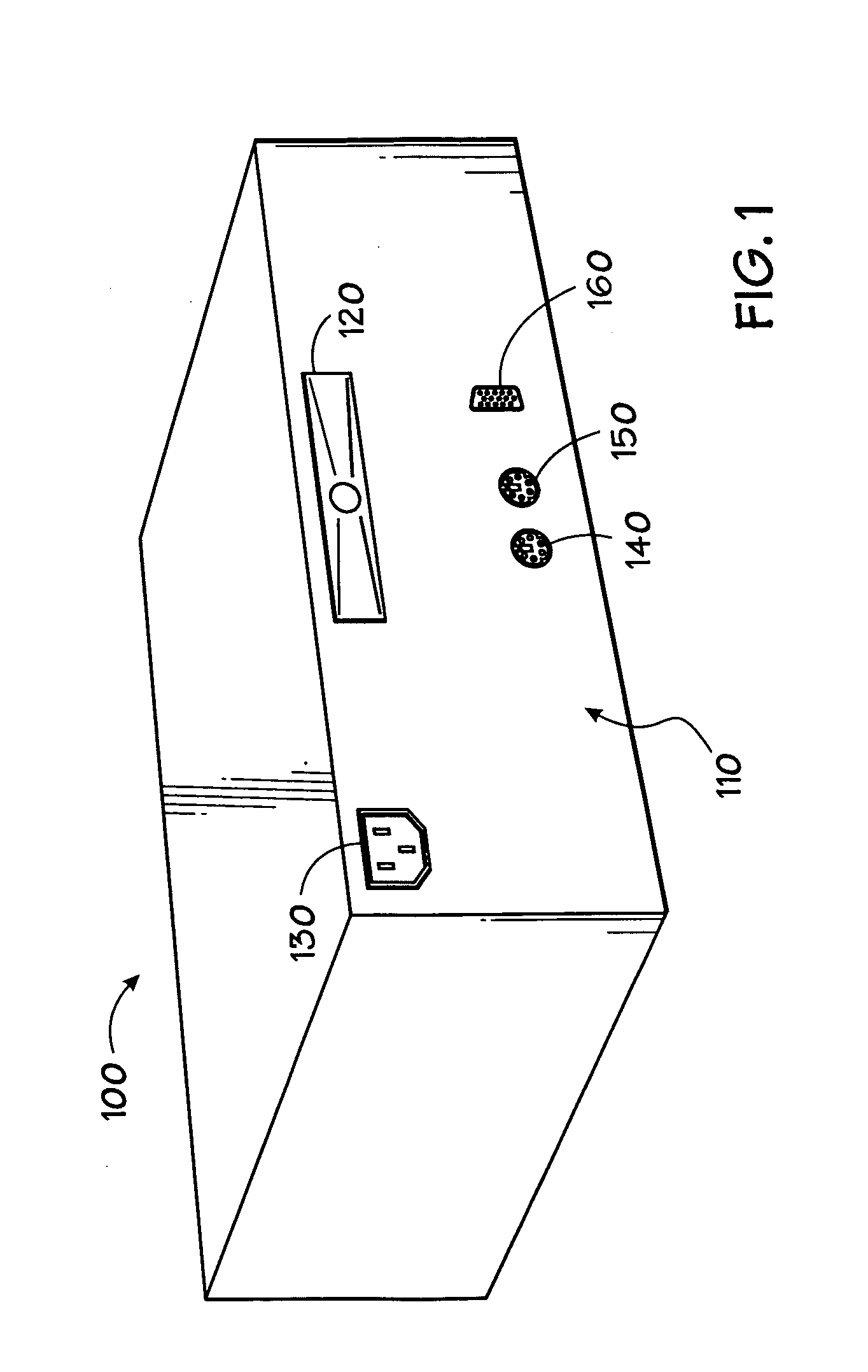
[0073]FIG. 1 shows a sample computer system according to the presently preferred embodiment. A rear view of computer system 100 shows a back panel 110 comprising a rear-firing acoustic driver designed for free-space operation 120, a power connector 130, a keyboard connector 140, a mouse connector 150, and a display connector 160. The driver 120 preferably has a QTS in the range of 0.65 to 0.8.

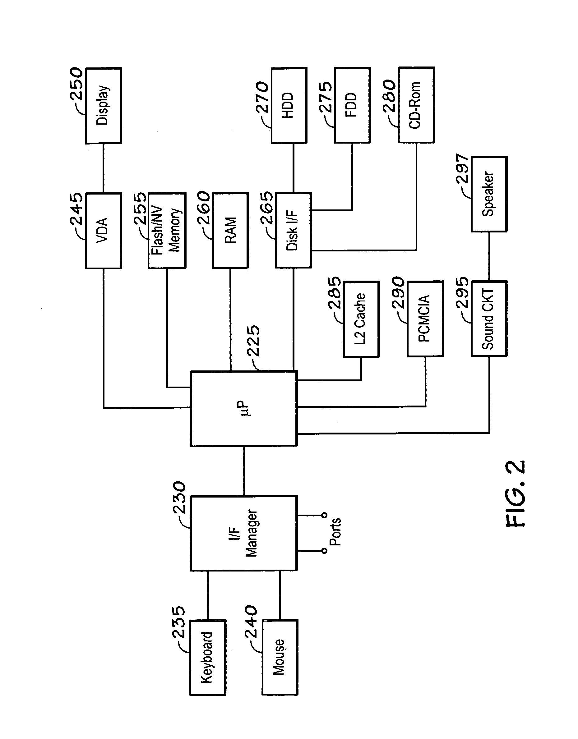
[0074]FIG. 2 shows a block diagram of the electrical organization of a sample computer system according to the presently preferred embodiment. The computer system includes in this example: user input devices (e.g. keyboard 235 and mouse 240); at least one microprocessor 225 which is operatively connected to receive inputs from said input device, through an interface manager chip 230 (which also provides an interface to the various ports); a memory (e.g. flash or non-volatile memory 255 and RAM 260), which is accessible by the microprocessor; a data output device (e.g. display 2...


PUM


Abstract

A desktop computer which has a driver mounted in the back wall of the chassis. The chassis is acoustically a very leaky box, so the driver is designed as if it were a free-space driver (using large cone area and long throw). In one class of embodiments, a single driver is used, and is centered in the back of the box so that there is an equal left-right split, although not true stereo. The front of the box may be made more acoustically leaky to move the acoustic image forward. The treatment of the box as being acoustically leaky means that the airflow required for thermal management has not been restricted. The use of a long-throw driver permits the volume-velocity of the driver to be increased. Treatment of the box as very leaky also means that no user changes or custom configurations will significantly disturb the expected acoustic environment. An audio system incorporating a free-space driver with an equalizer designed for use with a free-space driver further improves acoustic quality. Gain staging may also be used to improve acoustic quality of the audio system.

Description

BACKGROUND AND SUMMARY OF THE INVENTION[0001]The present application relates to computers with built-in speaker systems, and particularly to single-user desktop computers.[0002]Background: Computer-Based Audio[0003]The production of quality sound systems for computers has advanced significantly in recent years. Early personal computers typically had nothing more than a single, small acoustic driver used to produce a beep or series of single-frequency beeps to indicate system status upon startup. Typically, no additional sound producing circuitry was included. However, consumers demanded better audio performance. With recent advances in circuit miniaturization and audio engineering, sound cards capable of excellent sound reproduction are available for desktop computers.[0004]Background: Computer Audio Requirements[0005]In the 1990s, multimedia systems for personal computers have been a very active area of competition between manufacturers. The consumer market strongly demands some so...

Claims


Application Information

Patent Timeline
IPC IPC(8): H04R1/02H04R9/06
CPCH04R1/025H04R2499/15
Inventor MARKOW, MITCHELL A.GOUGH, DAVID E.
Owner HEWLETT PACKARD DEV CO LP
Learn More