
Method and apparatus for optical interactance and transmittance measurements

a technology of transmittance measurement and optical interaction, applied in the field of optical interactionance and transmittance measurement, can solve the problems of inconvenient handling of intact small samples, nonlinearity is predictable, and the nonlinear signal is not linear, so as to minimize the inaccuracy of spectroscopic determination and improve the optical interaction measurement

Inactive Publication Date: 2006-11-28
STARK EDWARD W
View PDF24 Cites 19 Cited by
  • Summary
  • Abstract
  • Description
  • Claims
  • Application Information

AI Technical Summary

Benefits of technology

[0012]In accordance with the invention, a method for improving optical interactance measurements comprises the steps of providing illumination by way of a plurality of paths through a specimen having a characteristic to be measured, sensing two or more independent signals developed at the same time or in rapid sequence representing optical information from said specimen and processing said signals in accordance with appropriate modeling techniques to minimize inaccuracies in spectroscopic determination of qualitative .of quantitative characteristics of the specimen.
[0013]Also in accordance with the invention, apparatus for improving optical interactance measurements comprises means for providing illumination through a specimen having a characteristic to be measured along a plurality of different paths, means for sensing optical information provided from an illuminated specimen, means for developing a plurality of independent signals corresponding in number to said plurality of paths, the signals representing the optical information obtained from the specimen and means for processing the signals in accordance with appropriate modeling techniques to minimize inaccuracies in spectroscopic determination of quantitative or qualitative characteristics of the specimen.

Problems solved by technology

This results in a very nonlinear signal relative to concentration of an analyte within the specimen, however, the nonlinearity is predictable based on the known optical geometry of the cell.
These methods for handling intact small samples have been inconvenient at best.

Method used


Image

  • Method and apparatus for optical interactance and transmittance measurements
  • Method and apparatus for optical interactance and transmittance measurements
  • Method and apparatus for optical interactance and transmittance measurements

Examples


Embodiment Construction

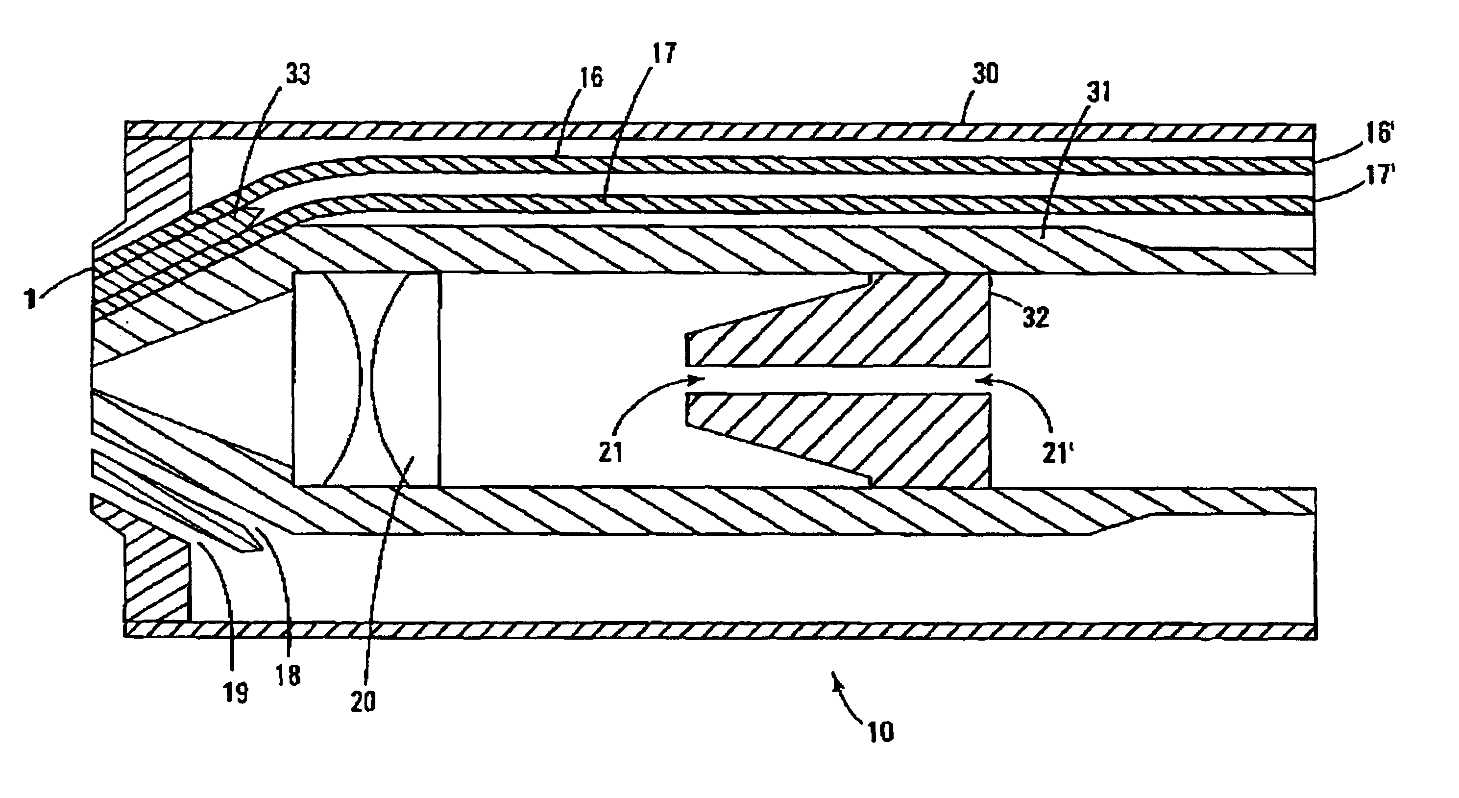
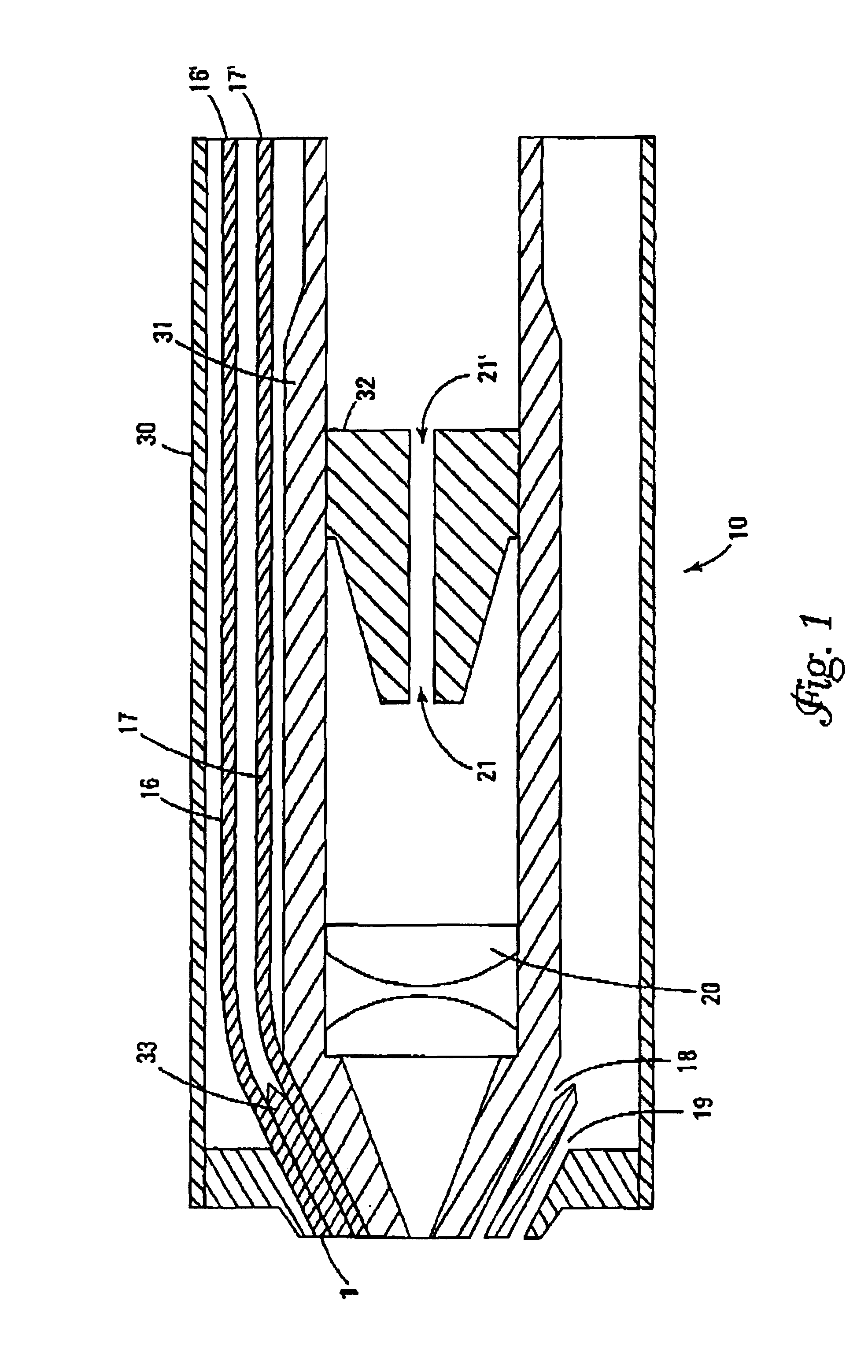
[0018]A first aspect of this invention comprises the use of three or more optical apertures shared among the source and illumination functions so as to provide two or more independent signals for further processing and analysis. For example, in FIG. 1 a probe utilizing fiber optics is shown which has two ring apertures surrounding a central round aperture.

[0019]In FIG. 1 the probe 10 includes a cylindrical outer body 30 in which a concentric inner body 31 is arranged. The inner body 31 tapers at the examining end to a central aperture 15. The outer body 30 constricts at the examining end to define a conical, inwardly directed wall. The tapered end of the inner body 31 defines a second conical wall. Between these two walls 30, 31 is disposed a conical dividing element 33. The angles defined by the two walls and the conical dividing element are preferably the same. Conical annular spaces or rings (shown in cross-section as 14, 13, 12 and 11) are defined by the two walls and dividing e...


PUM


Abstract

Apparatus and a method are disclosed for the simultaneous or rapid sequential use of two or more different separations between the source and detector of the measuring apparatus to obtain spectral measurement data in diffuse transmission or “interaction” modes of collecting optical information from a specimen. The method and apparatus subsequently combine separate data taken from two or more different pathlengths to provide discrimination against undesired information while preserving or enhancing desired information. Additional reference information to normalize the optical signal is also provided. The optical and mechanical design of the optical probe also provides for transmittance, reflectance and interactance measurements on small amounts of specimen.

Description

[0001]This is a continuation of application Ser. No. 08 / 062,738, now abandoned filed May 14, 1993, which is a Cont. of 07 / 663,144, filed Mar. 1, 1991, abandoned.[0002]This is a continuation of U.S. patent application Ser. No. 08 / 385,073, filed on Feb. 7, 1995, now abandoned.FIELD OF THE PRESENT INVENTION[0003]The present invention relates to an improved method and apparatus for performing optical interactance and transmittance measurements and, in particular, such method and apparatus where undesired information is discriminated against and desired information is enhanced. Reflectance measurements on small amounts of specimen are also encompassed by the invention.BACKGROUND OF THE PROBLEMSOLVED BY THE PRESENT INVENTION[0004]When optical energy is transmitted through a diffuse medium, scattering causes redirection of the rays so that the geometric pathlength between the energy entrance point and the energy exit point no longer defines the distance energy travels within the specimen. ...

Claims


Application Information

Patent Timeline
IPC IPC(8): G01N21/47
CPCG01N21/255G01N21/474
Inventor STARK, EDWARD W.
Owner STARK EDWARD W
Learn More