
Monitoring and analysis of data in cyberspace

a data monitoring and cyberspace technology, applied in the field of data monitoring and analysis systems, can solve problems such as system serious undesirable consequences, operator frustration, and the amount of available destination data, and achieve the effects of greater efficiency, greater reliability, and faster training

Inactive Publication Date: 2006-11-28
CALIFORNIA INST OF TECH
View PDF5 Cites 29 Cited by
  • Summary
  • Abstract
  • Description
  • Claims
  • Application Information

AI Technical Summary

Benefits of technology

The invention described in this patent was made while working for NASA and is subject to certain legal provisions. The technical effect of this patent is that it describes a new invention that was created while working for a specific organization. The organization has chosen to keep the invention for themselves, and the patent text explains the legal details of this decision.

Problems solved by technology

In extreme cases, these actions may save the system from serious undesirable consequences.
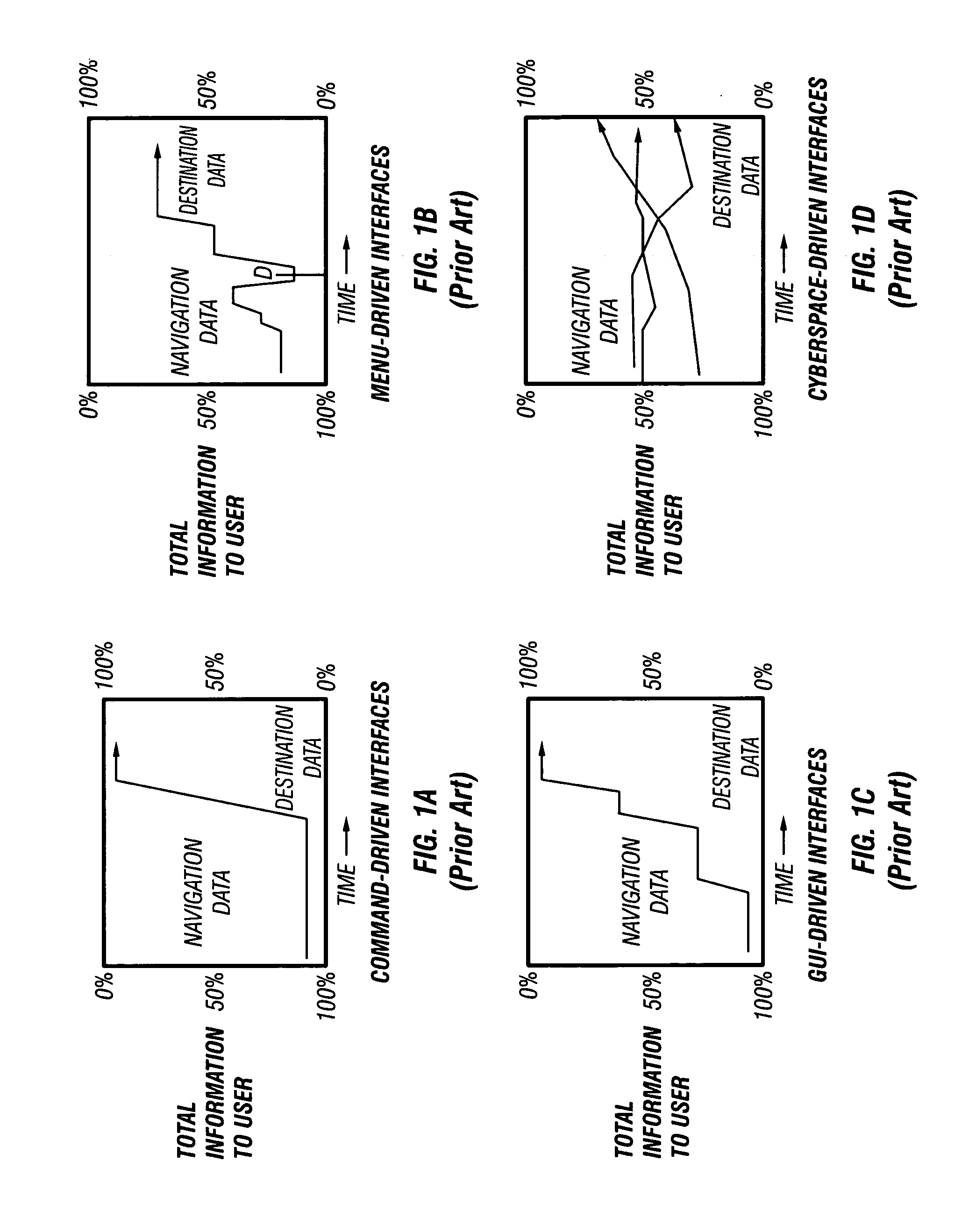
However, the operator can become frustrated upon encountering several layers of sub-menus before being able to access the bulk of the destination data.
This results in a drop-off (at time D in FIG. 1b) in the amount of available destination data.
Certain destination data may not be accessible until the operator has stepped through a number of windows, thus diminishing the operator's efficiency.
Monitoring this data poses a daunting and complex challenge.
As spacecraft and their associated instruments became more sophisticated, light-panel monitoring systems became inadequate to handle the volume and complexity of the telemetry data that was being collected.
Light-panel systems also were difficult and labor-intensive to adapt for new types of telemetry data that changed with each mission.
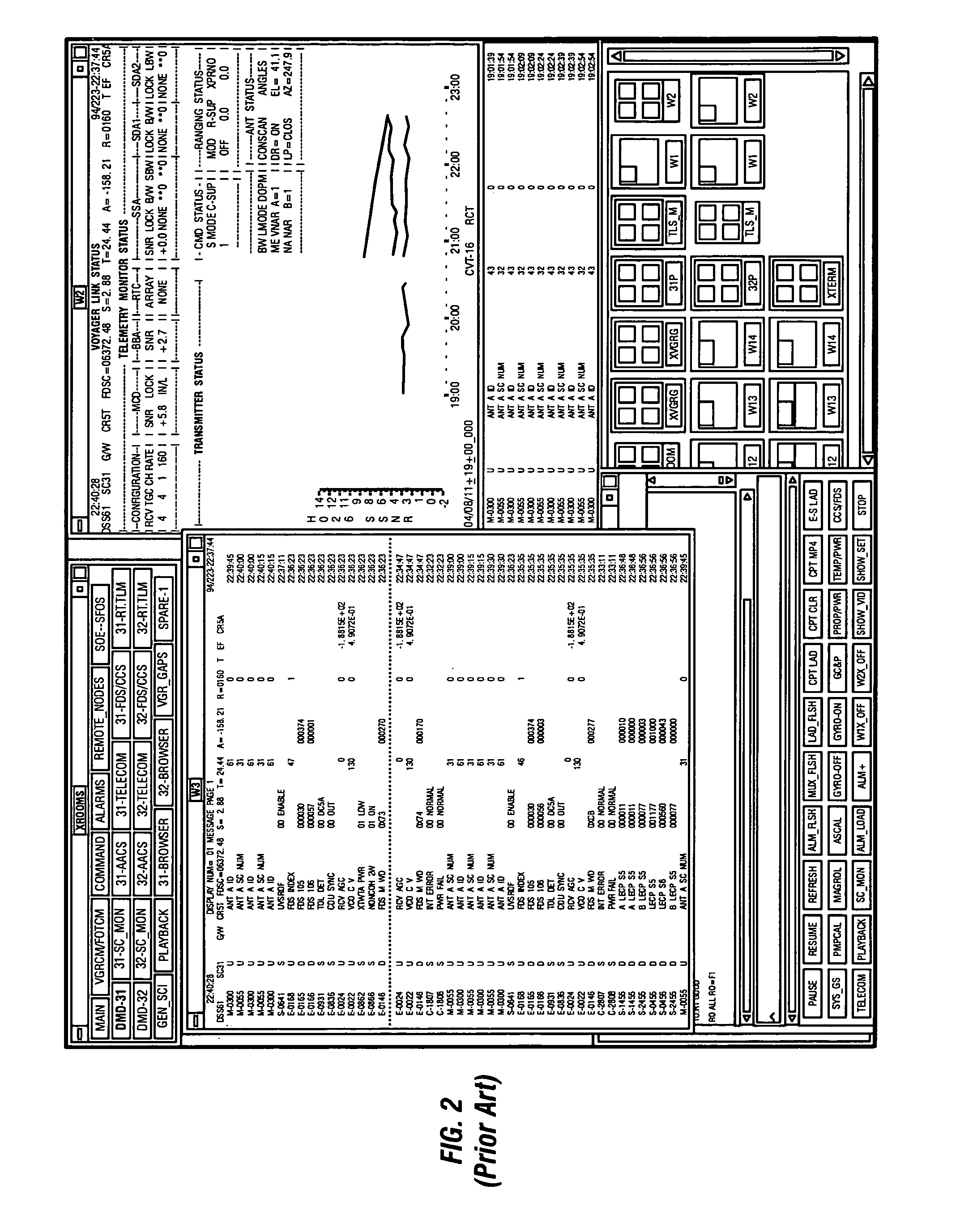
The necessarily high volume of telemetry data causes the display screen to become cluttered and difficult to read.
That task requires extensive training and considerable diligence on the operator's part.
Even with sufficient training, using a text-based system to monitor data is fatiguing for the operator and frequently results in missed alarm conditions or slow responses to alarm conditions.
In short, text-based data monitoring systems do not generate easily recognizable indicators of changes in system status.

Method used


Image

  • Monitoring and analysis of data in cyberspace
  • Monitoring and analysis of data in cyberspace
  • Monitoring and analysis of data in cyberspace

Examples


Embodiment Construction

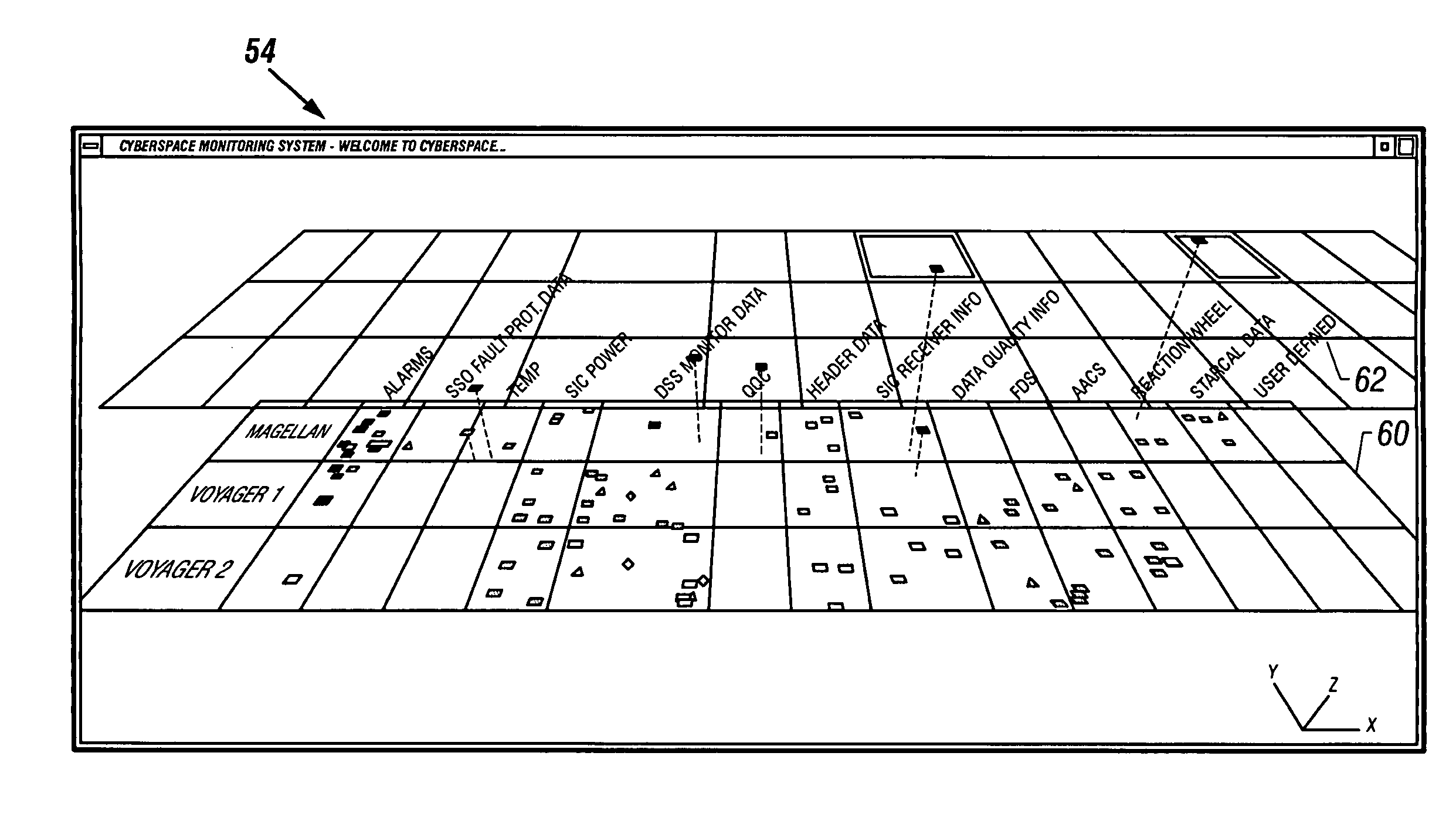
[0039]FIG. 3 shows a preferred embodiment of the cyberspace data monitoring system (CDMS) 10 of the present invention. The CDMS 10 has special features which facilitate monitoring and control of one or more complex monitored systems 14, 16 and 18 by an operator. The operator may be required to quickly assess the real-time status of the monitored systems 14–18 and to make appropriate decisions regarding necessary responses to the system status.

[0040]Data from the monitored systems 14–18 is processed by a conventional host computer 20 which includes a CPU 22, memory 24 and IO unit 26. Host 20 may preferably comprise a UNIX or PC workstation. The host 20 also includes a cyberspace user interface 28 which contains the necessary computer programs and / or operating systems operating to implement the techniques of the invention. A transmitting unit such as a modem 29 is optionally employed for notifying an operator of a situation by means such as paging, in addition to a visual display.

[004...


PUM


Abstract

Information from monitored systems is displayed in three dimensional cyberspace representations defining a virtual universe having three dimensions. Fixed and dynamic data parameter outputs from the monitored systems are visually represented as graphic objects that are positioned in the virtual universe based on relationships to the system and to the data parameter categories. Attributes and values of the data parameters are indicated by manipulating properties of the graphic object such as position, color, shape, and motion.

Description

[0001]This is a continuation of U.S. application Ser. No. 08 / 797,769, filed Feb. 7, 1997 now U.S. Pat. No. 6,222,547.ORIGIN OF INVENTION[0002]The invention described herein was made in the performance of work under a NASA contract, and is subject to the provisions of Public Law 96-517 (35 USC 202) in which the Contractor has elected to retain title.FIELD OF THE INVENTION[0003]This invention relates to a data monitoring and analysis system. More specifically, the present invention defines a user interface providing a three dimensional representation of complex data, data relationships and system status.BACKGROUND AND SUMMARY OF THE INVENTION[0004]The operation of many complex systems requires an operator to monitor status of the system by assimilating a large amount of real-time status data received from various system components. Complex systems of this type include spacecraft operations, industrial plants, financial trading activities, and hospital monitoring of medical data from p...

Claims


Application Information

Patent Timeline
Patent Type & Authority Patents(United States)
IPC IPC(8): G06T11/20
CPCG06T11/206
Inventor SCHWUTTKE, URSULA M.ANGELINO, ROBERT
Owner CALIFORNIA INST OF TECH
Learn More