
Finned heat dissipation module having flow guide

a technology of heat dissipation module and flow guide, which is applied in the direction of laminated elements, lighting and heating apparatus, and semiconductor/solid-state device details. it can solve the problems of limiting the heat exchange between the airflow, the efficiency of heat removal is not optimal, and the power consumption of a computer device is dramatically increased. , to achieve the effect of enhancing heat exchange, extending the time, and increasing the contact surface area

Inactive Publication Date: 2006-11-28
MITAC TECH CORP
View PDF12 Cites 16 Cited by
  • Summary
  • Abstract
  • Description
  • Claims
  • Application Information

AI Technical Summary

Benefits of technology

This design improves heat removal efficiency by increasing the contact surface area and extending airflow time through the channel, leading to more effective heat exchange and reduced noise.

Problems solved by technology

The development of computer technology makes the power consumption of a computer device dramatically increased.
However, such a linear configuration limits heat exchange between the airflow and the fins for air flows through the fins quickly.
As a consequence, the efficiency of heat removal is not optimal and the life span of the computer or electronic components is often reduced.
Although heat can be effectively carried out by the heat dissipation module described above, the heat dissipation module cannot offer the optimum efficiency in removing heat and usually makes great noises.

Method used


Image

  • Finned heat dissipation module having flow guide
  • Finned heat dissipation module having flow guide
  • Finned heat dissipation module having flow guide

Examples


Embodiment Construction

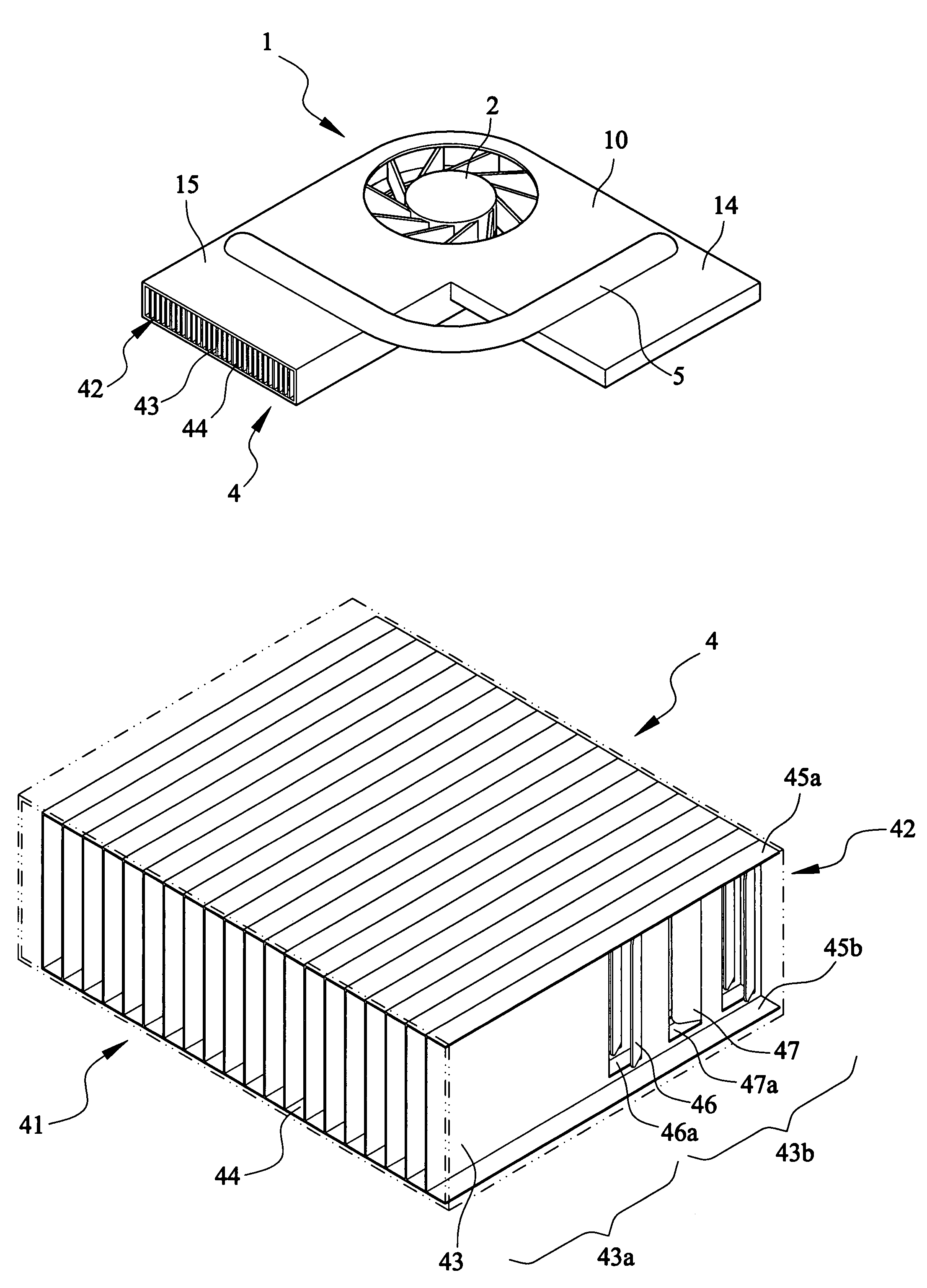
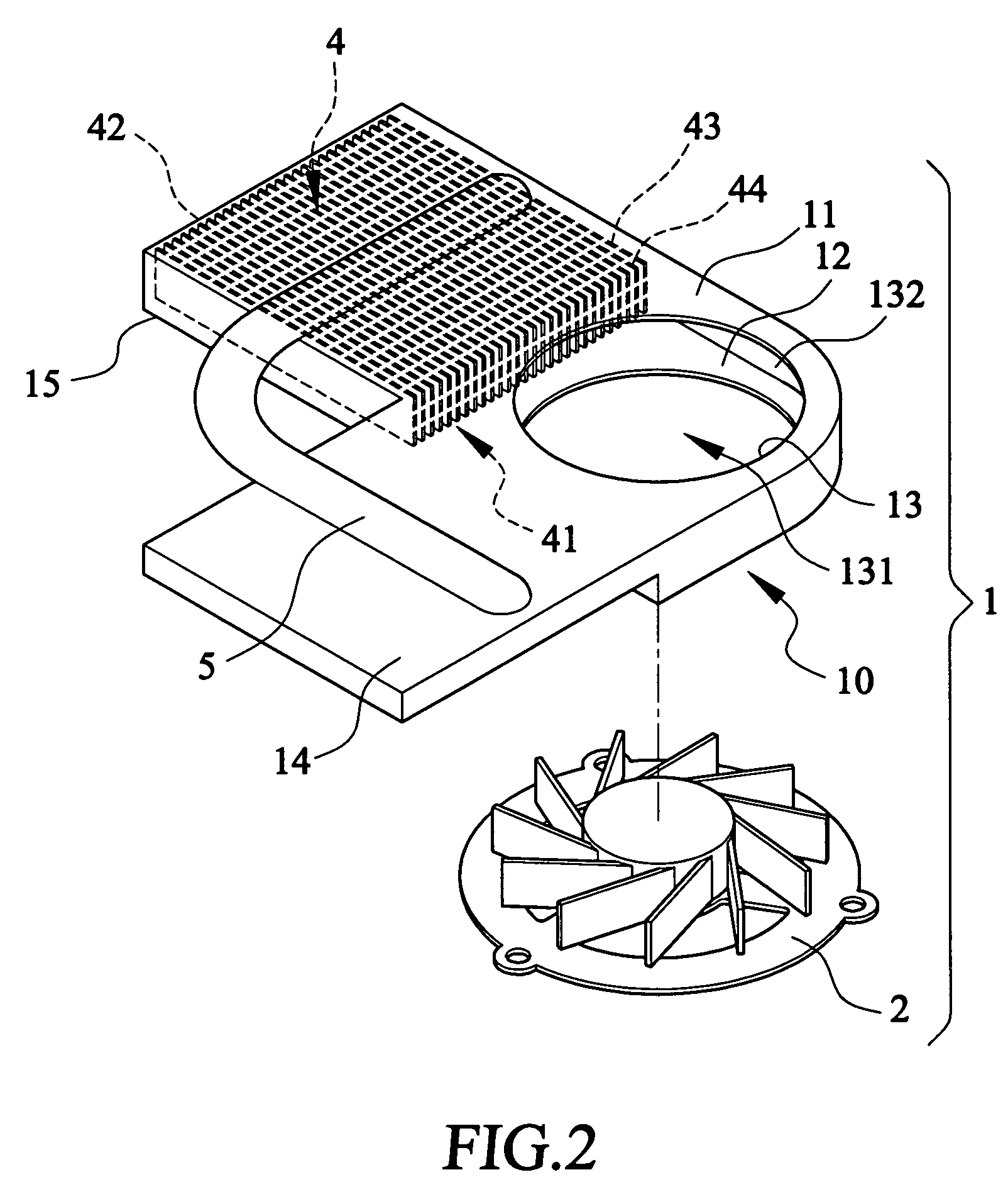
[0024]With reference to the drawings and in particular to FIGS. 2 and 4, a heat dissipation module constructed in accordance with the present invention, generally designated with reference numeral 1, comprises a casing or cartridge 10 made of thermally conductive material, comprised of a top panel 11 and a bottom panel 12 opposite to the top panel 11 with an interior space defined between the top and bottom panels 11, 12. Aligned openings (not labeled) are defined in the top and bottom panels 11, 12 to form a fan chamber 13 that receives and fixes an electric fan 2. The opening defined in the top panel for the fan 2 also constitutes an air intake opening 131 through which surrounding air may be drawn into the interior space of the casing 10 by the fan 2. A side opening 132 formed between outer edges of the top and bottom panels 11, 12 also provides an intake entrance for surrounding air into the interior space of the casing 10 by being drawn by the fan 2.

[0025]Also referring to FIG....


PUM


Abstract

A heat dissipation module includes an airflow generation device that generates airflow into an air channel in which a fin module is received and fixed. The fin module includes a plurality of fin plates substantially parallel to and spaced from each other to define air passages extending from an inlet to an outlet of the air channel. Each fin plate has a trailing section extending to the outlet and forming at least one inclined guide tab and an opening defined in the fin plate immediately close to the guide tab for switching at least a portion of the air between adjacent air passages on opposite sides of the fin plate. This increases the length of the path that the air flows through the air channel and thus raises the amount of heat exchanged between the fin plates and the air thereby enhancing efficiency of heat removal.

Description

BACKGROUND OF THE INVENTION[0001]1. Field of the Invention[0002]The present invention relates generally to a heat dissipation module comprising fins, and in particular to a finned heat dissipation module having guides for switching airflow between different air passages to enhance efficiency of heat dissipation.[0003]2. Description of the Prior Art[0004]The development of computer technology makes the power consumption of a computer device dramatically increased. Thus, a heat dissipation module is commonly employed in the recent computer devices or other electronic devices to remove heat from the computer or electronic components that generate heat in order to maintain proper operation temperature of the computer or electronic devices. Some heat dissipation devices incorporate a fan that induces air streams flowing through the heat dissipation device to facilitate heat removal by forced heat convection.[0005]Some conventional heat dissipation devices are comprised of fins arranged i...

Claims


Application Information

Patent Timeline
Patent Type & Authority Patents(United States)
IPC IPC(8): H05K7/20F28F3/04H01L23/367H01L23/427H01L23/467
CPCF28D15/0266F28F1/325H01L23/3672H01L23/427H01L23/467H01L2924/0002H01L2924/00
Inventor CHANG, JUEI-CHI
Owner MITAC TECH CORP
Learn More