
Apparatus and method for bending glass using microwaves

Active Publication Date: 2006-11-28
GUARDIAN GLASS LLC
View PDF36 Cites 24 Cited by
  • Summary
  • Abstract
  • Description
  • Claims
  • Application Information

AI Technical Summary

Benefits of technology

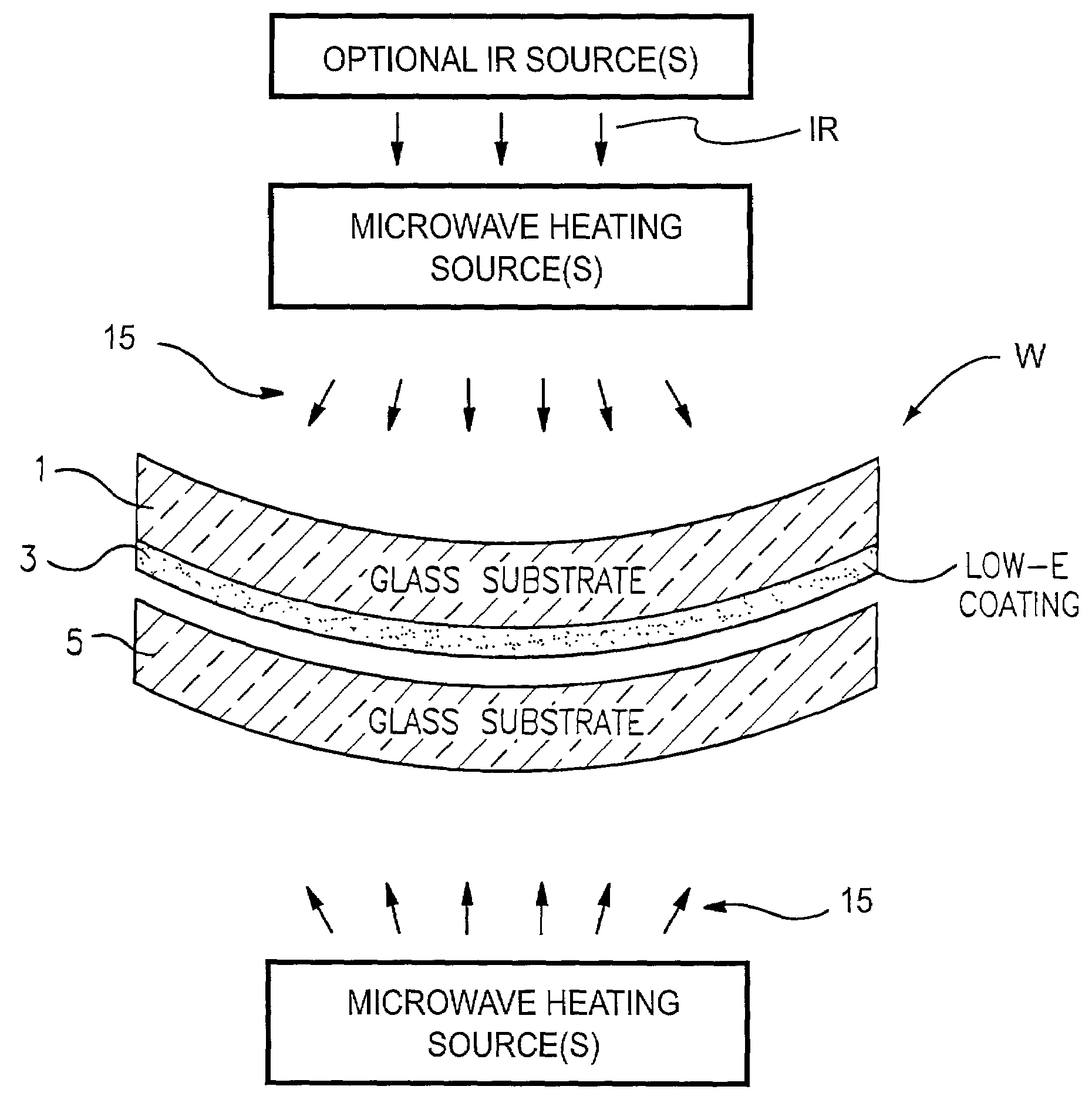
[0014]An object of this invention is to minimize the peak temperature attained (and/or the time at which a peak temperature is attained) by a solar control coating 3 during a process for heat bending a glass substrate that supports the coating.
[0015]Another object

Problems solved by technology

Unfortunately, it has been found that when using conventional glass bending techniques, certain solar control coatings cannot on a regular basis withstand the bending process(es) sometimes used without suffering damage, especially when very tight radius of curvature(s) are required for the windshield.
However, windshields having a smaller (or more extreme) tightest radius of curvature are sometimes required, and thus cannot be consistently made using IR heating techniques without damaging the aforesaid coating.
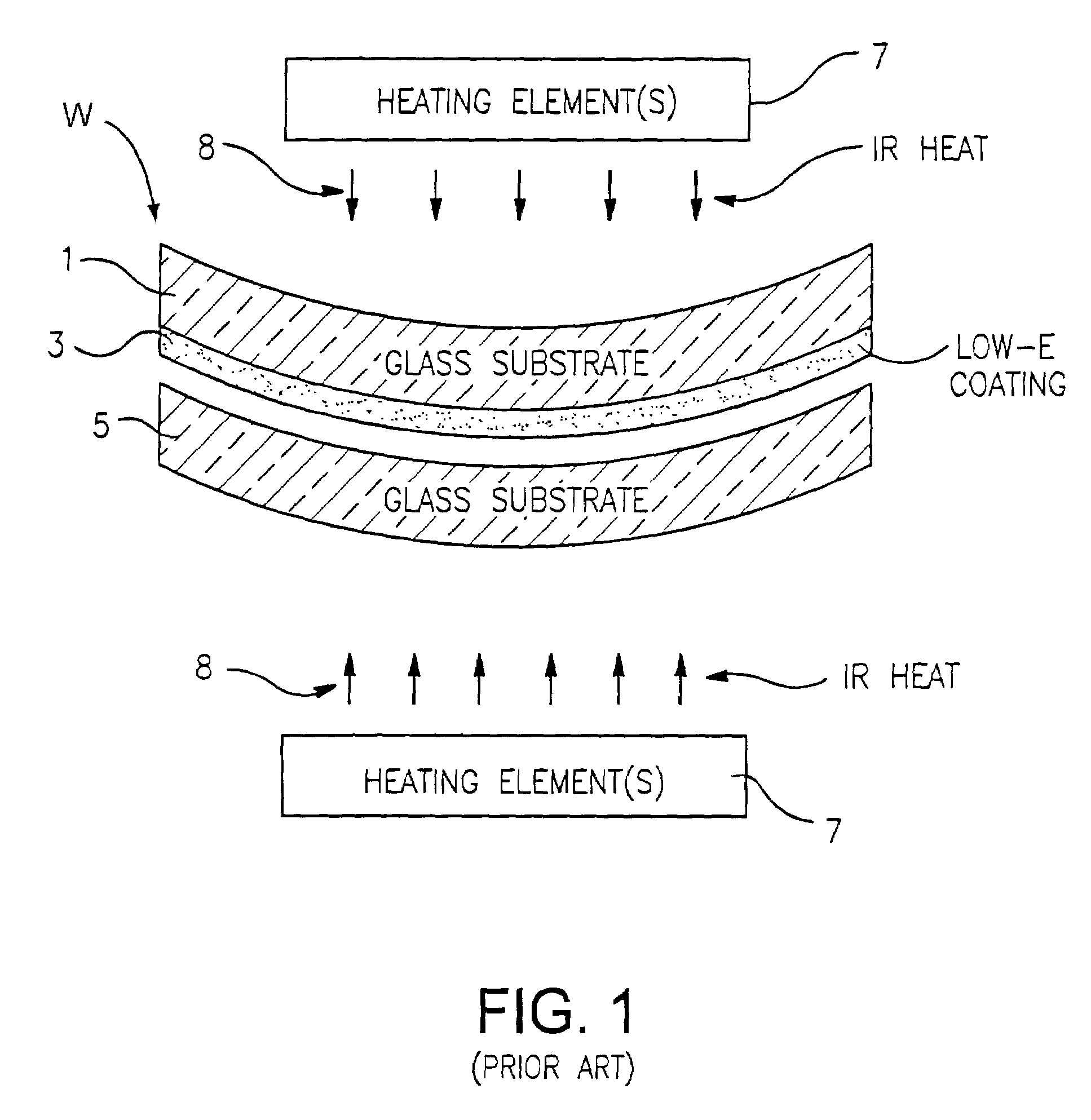
Unfortunately, this means that a significant amount of IR radiation in the near-IR range (from 0.7 to 3–4 μm) is not absorbed by the glass substrate(s) 1 and / or 5 and as a result passes therethrough and reaches solar control coating 3.
Unfortunately, certain of this near-IR radiation which is not absorbed by the glass substrate and reaches solar control coating 3, is absorbed by the coating 3 (e.g., by Ag layer(s) of the coating) thereby causing the coating 3 to heat up.
Coating 3 is more susceptible to being damaged when it is unnecessarily heated up during the glass bending process.
When coating 3 is damaged, the bent glass substrate 1 with the damaged coating thereon is typically discarded and cannot be commercially used.
This problem (i.e., coating overheating) affects the shapes that can be attained in the bending process.
In particular, more extreme glass bending requires more extreme heating (i.e., at higher temperatures and / or for longer times) of the glass to be bent.
This is, or course, undesirable if a portion of a windshield is desired to have a tighter (smaller) radius of curvature; i.e., to be more bent.
In other words, the '345 patent fails to disclose or suggest using microwave radiation to heat coated glass sheet(s) for the purpose of enabling the coated glass sheet(s) to be bent to a more significant degree or smaller tightest radius of curvature.

Method used


Image

  • Apparatus and method for bending glass using microwaves
  • Apparatus and method for bending glass using microwaves
  • Apparatus and method for bending glass using microwaves

Examples


Embodiment Construction

[0029]Referring now more particularly to the accompanying drawings in which like reference numerals refer to like parts throughout the several views.

[0030]FIG. 4 is a schematic diagram of an apparatus and method for bending glass substrate(s) / sheet(s) according to an example embodiment of this invention. Glass sheets or substrates bent herein may be used in applications such as vehicle windshields, other types of laminated or monolithic windows, IG window units, or any other suitable application.

[0031]According to certain example embodiments of this invention, it has surprisingly been found that the use of at least microwave energy to heat a coated glass substrate to be bent enables the glass substrate to be bent while the maximum temperature achieved / realized (and / or the time period for which a maximum temperature is achieved) by the coating supported by the substrate during the bending process is reduced. By reducing the maximum temperature achieved by the coating during the bendi...


PUM

PropertyMeasurementUnit
Lengthaaaaaaaaaa
Lengthaaaaaaaaaa
Radiusaaaaaaaaaa

Abstract

An apparatus and method for bending glass substrate(s) are provided. Microwave radiation is used to heat glass substrate(s) for bending. As a result, a coating supported by the substrate(s) is not heated as much during the bending process compared to if only conventional IR radiation was used. Thus, more extreme degrees of glass bending may be achieved, and / or the likelihood of coating damage reduced.

Description

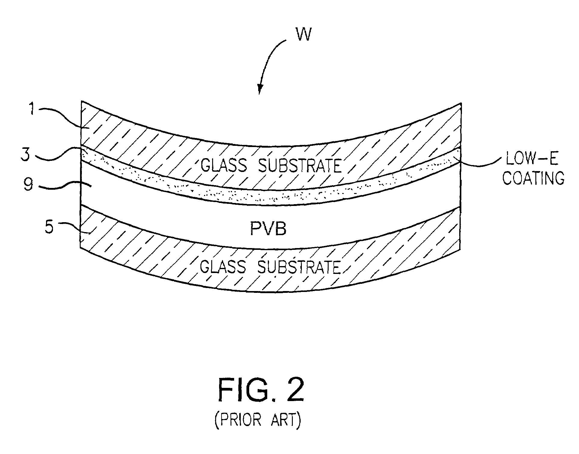
[0001]This invention relates to an apparatus and method for heat bending glass sheets. More particularly, this invention relates to an apparatus and method for bending coated glass sheets by directing microwave radiation (waves) at the glass sheet(s) in order to heat the same.BACKGROUND AND SUMMARY OF THE INVENTION[0002]Devices and methods for heat bending glass sheets are well known in the art. For example, see U.S. Pat. Nos. 5,383,990; 6,318,125; 6,158,247; and 5,443,669.[0003]FIG. 1 is a schematic diagram illustrating a conventional apparatus and method for heat bending glass sheets in making a laminated product such as a vehicle windshield. Vehicle windshields are typically curved, and thus require first and second curved (as a result of heat bending) glass sheets laminated to one another via a polymer interlayer. First glass substrate 1 has a multi-layer solar control coating 3 thereon (e.g., low-E coating 3 including at least one IR reflecting layer of a material such as Ag); ...

Claims


Application Information

Patent Timeline
IPC IPC(8): C03B23/023B32B17/10C03B29/00C03B29/02C03C23/00
CPCB32B17/10036B32B17/10174B32B17/10761B32B17/10889C03B29/00C03B29/025C03C23/0065Y02P40/57
Inventor VANDAL, ROBERT A.
Owner GUARDIAN GLASS LLC
Learn More