Optical communication system

a communication system and optical technology, applied in the field of optical communication systems, can solve the problems of imposing a severe limitation on the communication bandwidth which can theoretically be provided, limiting the bandwidth of the communication system, and not divulging the practical hardware for such routing

Inactive Publication Date: 2006-11-14
TELEFON AB LM ERICSSON (PUBL)
View PDF27 Cites 6 Cited by
  • Summary
  • Abstract
  • Description
  • Claims
  • Application Information

AI Technical Summary

Benefits of technology

[0023]The invention provides the advantage that the system is capable of addressing one or more of the aforementioned first, second and third problems.
[0028]Such an implementation of the coupling means is convenient because the means can be purchased as a compact and cost effective unit from commercial suppliers, for example from specialist optical component suppliers in the USA, Canada and Japan.
[0036]In the system, it is advantageous that the paths support bi-directional radiation propagation therealong to provide security should the path become defective in one of its propagation directions, and also to distribute communication traffic more uniformly within the system. Thus, it is beneficial that the first and second paths are operable to support bi-directional radiation propagation therealong, and the interfacing means is operable to couple radiation of one or more of the wavebands propagating in either direction along the first path to the second path for propagation in either direction therealong.
[0038]In some circumstances, it is advantageous to be able to redirect communication traffic associated with one or more selected wavebands from one direction along a path of the system to another direction therealong on order to distribute communication traffic load and also to achieve a shortest communication path from a transmitting node of the system to a receiving node thereof. Thus, it is beneficial that at least one of the paths of the system is operable to support bi-directional radiation propagation therealong, the at least one path including redirecting means for coupling radiation of one or more wavebands from a first direction of radiation propagation to a second direction of radiation propagation along the at least one path, the second direction being mutually oppositely directed to the first direction.

Problems solved by technology

However, as the number of radiation components changes, the power of each of the remaining components will be modified by such compensation which often represents a departure from optimum device operating conditions.
However, practical hardware for performing such routing is not disclosed in the publication.
In practice, converting optical radiation into corresponding electrical signals at each node in conventional systems imposes a severe limitation on the communication bandwidth which can theoretically be provided by these systems.
Such a limitation of bandwidth represents a serious first problem for the conventional systems.
It is not practicable to exploit soliton wave propagation in conventional optical communication systems on account of frequent conversions between modulated optical radiation and corresponding electrical signals which occur in such systems; these conversions negate any potential benefits from exploiting soliton propagation.
The inventors have therefore devised a regenerative interface for a communication system, the interface capable of providing flexible re-routing of communication traffic whilst performing as much optical processing as possible; attempts so far in the prior art to provide an all-optical communication system have been frustrated by technical difficulties, particularly with regard to achieving all-optical reconfigurable radiation routing.
Moreover, the inventors have appreciated a second problem in conventional communication systems regarding bandwidth limitation arising from inefficient use of system wavebands.

Method used


Image

  • Optical communication system
  • Optical communication system
  • Optical communication system

Examples


Embodiment Construction

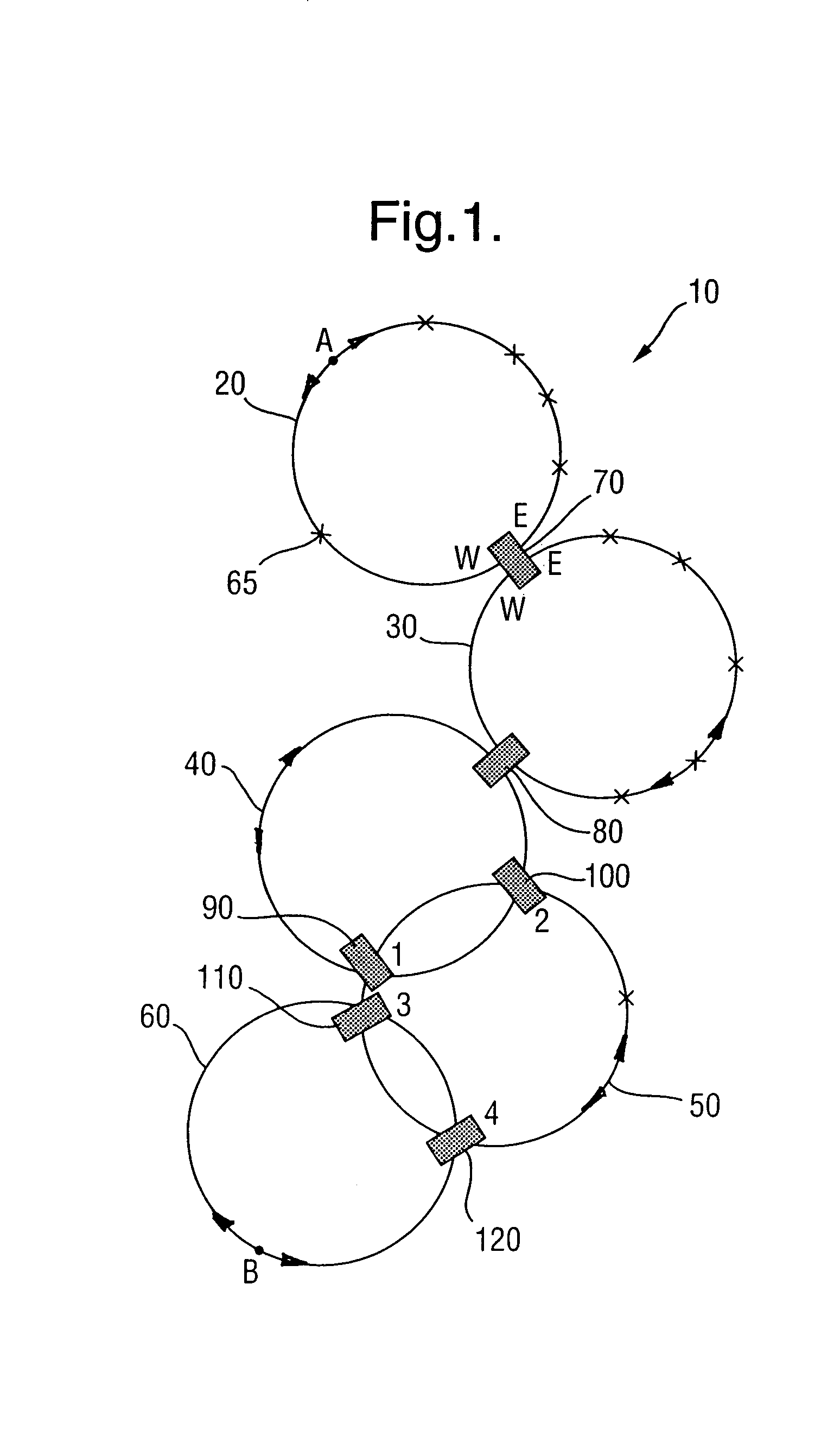
[0059]Referring now to FIG. 1, an optical communication system according to the invention is indicated generally by 10. The system 10 comprises five interlinked bi-directional optical communication rings 20, 30, 40, 50, 60. The rings 20, 30, 40, 50, 60 are of diameters in a range of 10 km to 100 km and are operable to provide communication links at national and regional level. The rings 20, 30 include repeater nodes, for example a repeater node 65, represented by crosses around the rings 20, 30. Moreover, the ring 20 is connected through an interface 70 to the ring 30. Likewise, the ring 30 is connected through an interface 80 to the ring 40. The ring 40 is connected at first and second positions thereon through interfaces 90, 100 respectively to the ring 50. Likewise, the ring 50 is connected at third and fourth positions thereon through interfaces 110, 120 respectively to the ring 60. The interfaces 70 to 120 are similar and will be described in more detail later.

[0060]Each of the...


PUM


Abstract

The invention provides an optical communication system (10) comprising a plurality of mutually interconnected bi-directional optical waveguide rings (20, 30, 40, 50, 60) in which radiation modulated with communication traffic propagates. The radiation is partitioned into 32 distinct wavebands. Interfaces (70, 80, 90, 100, 110, 120) are included in the system (10) where communication traffic propagating in the rings transfers from one ring to another. Each interface (70) is capable of providing an all-optical waveband reconfigurable communication link between the rings (20, 30, 40, 50, 60). At each interface (70), conversion of optical radiation to corresponding electrical signals is not required when transferring communication traffic from one ring to another, thereby providing the system (10) with a potentially larger communication bandwidth compared to conventional optical communication systems. If required, the interfaces (70, 80, 90, 100, 110, 120) can include one or more of regenerative amplification (440, 850, 852, 854, 856, 858, 860, 862, 864) and wavelength-switching transponders (1332, 1410).

Description

BACKGROUND OF THE INVENTION[0001]The present invention is concerned with an optical communication system, in particular, but not exclusively, with an optical communication system including interconnected optical communication rings. Moreover, the invention also relates to a method of operating such a system. Furthermore, the invention also relates to an interface for use in the system.[0002]Conventional optical communication systems comprise nodes interconnected by optical fibre waveguides. Communication traffic is communicated between the nodes by conveying optical radiation through the waveguides, the radiation being modulated by the communication traffic. Optical radiation in the context of the present invention is defined as electromagnetic radiation within a free-space wavelength range from 560 nm to 2000 nm, although a free-space wavelength of substantially 1550 nm is a preferred part of this range.[0003]Each node is operable to convert modulated radiation received thereat int...

Claims


Application Information

Patent Timeline
Patent Type & Authority Patents(United States)
IPC IPC(8): H04J14/02H04B10/02H04B10/16H04B10/17H04B10/24H04B10/29H04Q3/52H04Q11/00
CPCH04J14/0227H04J14/0283H04J14/0286H04Q11/0062H04J14/0241H04J14/021H04J14/0221H04Q2011/0011H04Q2011/0075
Inventor SHARRATT, MICHAELCLARINGBURN, HARRY R
Owner TELEFON AB LM ERICSSON (PUBL)
Why Eureka
Try Eureka