
Method and system for texturing

a texturing and method technology, applied in the field of graphics generation, can solve the problems of inability to account for surface thickness of existing texture-rendering techniques, and inability to accurately render a semi-opaque surface, etc., to avoid the inconvenience and delay of memory page swapping

Inactive Publication Date: 2006-11-14
SONY CORP +1
View PDF17 Cites 14 Cited by
  • Summary
  • Abstract
  • Description
  • Claims
  • Application Information

AI Technical Summary

Benefits of technology

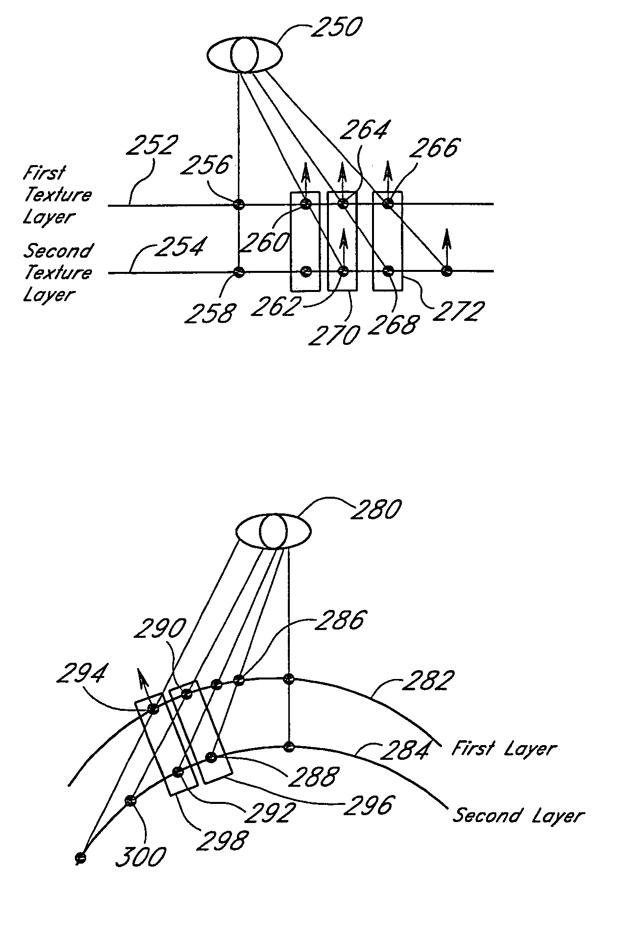
[0010]The present invention relates to a method and system for texturing. One aspect of the texturing system advantageously allows a hardware- or software-based polygon texturing engine to render surfaces that have an apparent thickness (i.e., surface depth), where the upper layers are partially transparent and sub-surface details at least partially show (i.e., become visible) through the upper layers.
[0012]The texturing system advantageously does not require additional polygon modeling or volumetric analysis and calculations to create the appearance of surface depth, as required in existing systems. In addition, when the surface does not have a depth component, the texturing system advantageously allows multiple textures to be applied in a single pass by a texturing engine. Thus, the texturing system minimizes the inefficiency of multi-pass rendering associated with conventional systems.
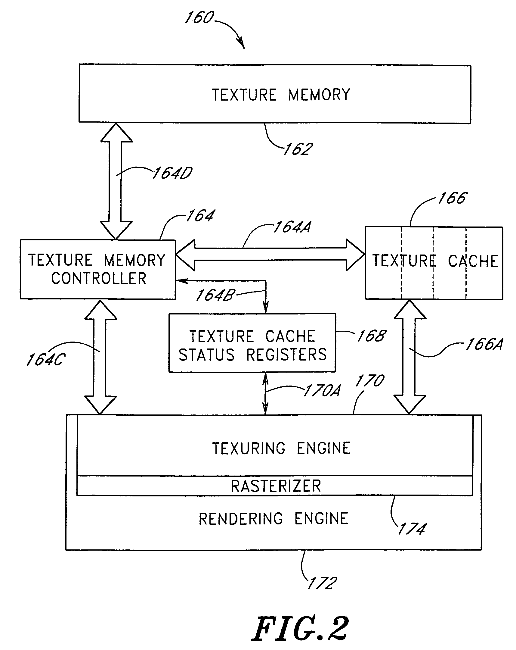
[0016]Another aspect of the texturing system provides a novel way of organizing texture memory and the addition of control registers and lookup tables to existing texturing hardware. The texture memory format advantageously avoids the inconvenience and delay of memory page swapping in conventional texture memory systems.

Problems solved by technology

Existing texture-rendering techniques are able to model a simple opaque surface, but are unable to accurately render a semi-opaque surface, where the upper layers of the surface are partially transparent, and reveal sub-surface details.
Existing texture-rendering techniques cannot account for surface thickness without either explicitly modeling all of the surface layers individually or by mathematically calculating the contents of the entire three-dimensional volume that encloses the surface.
Both of these techniques require additional hardware and / or software and may require a longer processing time.
Another problem with conventional texturing systems is the need to make multiple passes in order to apply multiple textures to a fragment, which is called ‘multi-texturing.’ Conventional texturing systems can only access and read one texture image (a MIP map set) at a time.
The multiple passes and other processes of conventional systems require a long processing time, which is undesirable to the user.

Method used


Image

  • Method and system for texturing
  • Method and system for texturing
  • Method and system for texturing

Examples


Embodiment Construction

[0030]FIG. 1A illustrates a first eye point position 100 above a plurality of texture layers comprising a first texture layer 102, a second texture layer 104, a third texture layer 106, and a fourth texture layer 108. Each texture layer 102, 104, 106, 108 comprises a texture map with all of its associated MIP (multum in parvo) maps. Texture mapping is described in “Computer Graphics Principles and Practice” by James D. Foley et al., 1997, on pages 741–744, and “Introductive Computer Graphics, A top-down approach with OpenGL” by Edward Angel, 1997, pages 389–397, which are hereby incorporated by reference in their entirety. MIP mapping is described on pages 826–828 of “Computer Graphics Principles and Practice.”

[0031]Each texture map comprises a plurality of texels. FIG. 1A illustrates a first texel 110 in the first texture layer 102, a second texel 112 in the second texture layer 104, a third texel 114 in the third texture layer 106 and a fourth texel 116 in a fourth texel layer 108...


PUM


Abstract

A method and system for texturing. The texturing system is configured to render surfaces that have an apparent thickness, where the upper layers of the surface are partially transparent and sub-surface details show through the upper layers. Interpolated stepping values provide parallax between various texture layers. The texturing system also provides a texture memory configured to store texture data as a plurality of packets. Each packet comprises texture data from at least two texture layers. A texture memory controller is configured to access one or more packets in the texture memory and pass the packets to a texturing engine.

Description

BACKGROUND OF THE INVENTION[0001]1. Field of the Invention[0002]The present invention relates to generating graphics. Specifically, the present invention relates to a method and system for texturing.[0003]2. Description of Related Art[0004]In computer graphics, existing texture-rendering techniques map a pixel on a screen (typically using screen coordinates (x, y)) to a polygon, such as a triangle, on a surface in a viewing plane (typically using geometric or surface coordinates (s, t)). The polygon is rasterized into a plurality of smaller pieces called fragments. Each polygon may have information, such as color and / or a normal vector, associated with each vertex of the polygon. To assign a texture (i.e., a color pattern or image, either digitized or synthesized) to a fragment, the fragment is mapped onto a texture map (typically using texture coordinates (u, v)). Texture maps are stored in a texture memory. A texture map represents a type of image, such as stripes, check.erboards,...

Claims


Application Information

Patent Timeline
Patent Type & Authority Patents(United States)
IPC IPC(8): G09G5/00
CPCG06T15/04
Inventor DAWSON, THOMAS PATRICK
Owner SONY CORP
Learn More