
Power supply rejection for pulse width modulated amplifiers and automatic gain control

a technology of power supply and modulation amplifier, applied in the direction of amplifier with semiconductor device/discharge tube, amplifier with volume compression/expansion, amplifier modification to reduce non-linear distortion, etc., can solve the problem of low implementation cost when used, and achieve the effect of improving power supply rejection, and little or no distortion

Inactive Publication Date: 2006-11-14
ALTEC LANSING LLC
View PDF2 Cites 11 Cited by
  • Summary
  • Abstract
  • Description
  • Claims
  • Application Information

AI Technical Summary

Benefits of technology

The solution provides improved power supply rejection with minimal signal distortion, allowing for efficient operation with smaller heat sinks and power transformers, and can be used in Class D amplifiers to maintain dynamic range and reduce harmonic distortion.

Problems solved by technology

The cost of implementation is lower than conventional designs when used in conjunction with a Class D amplifier.

Method used

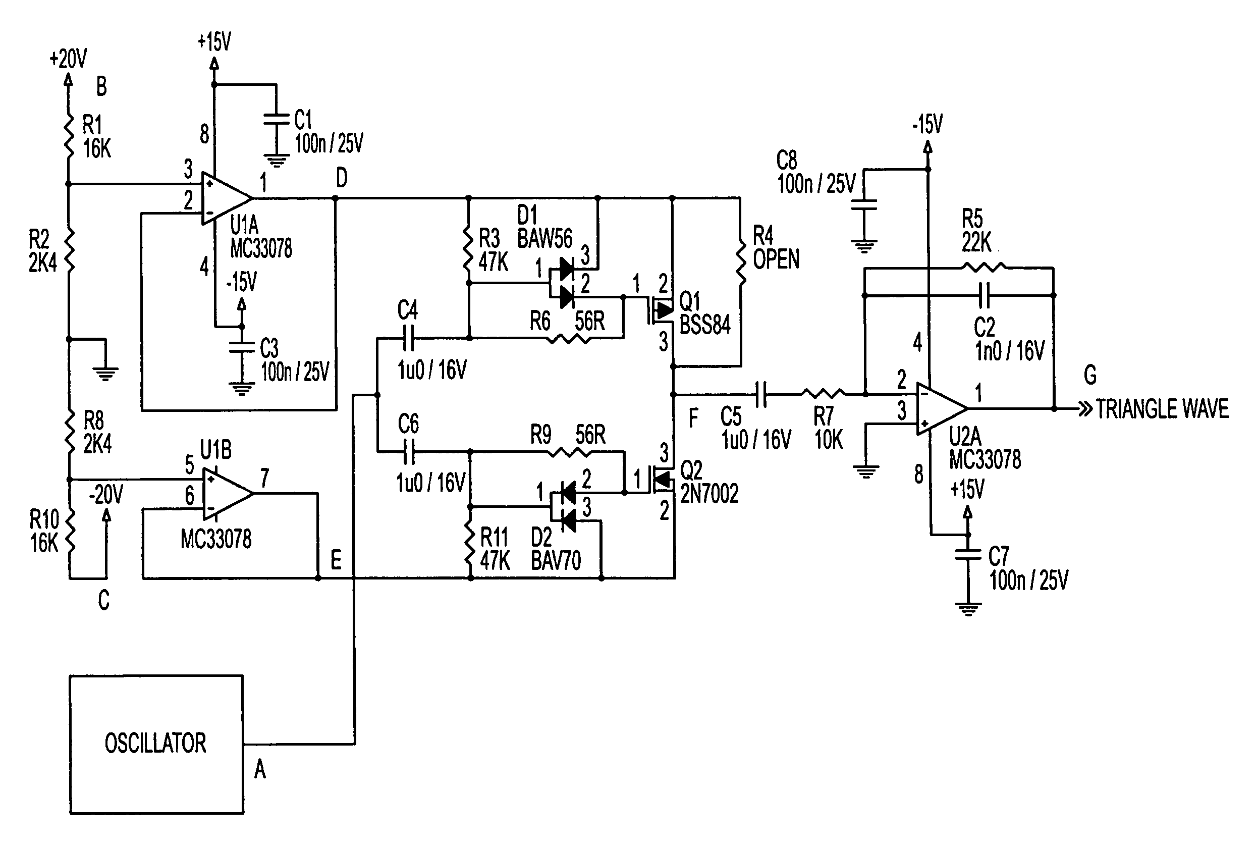
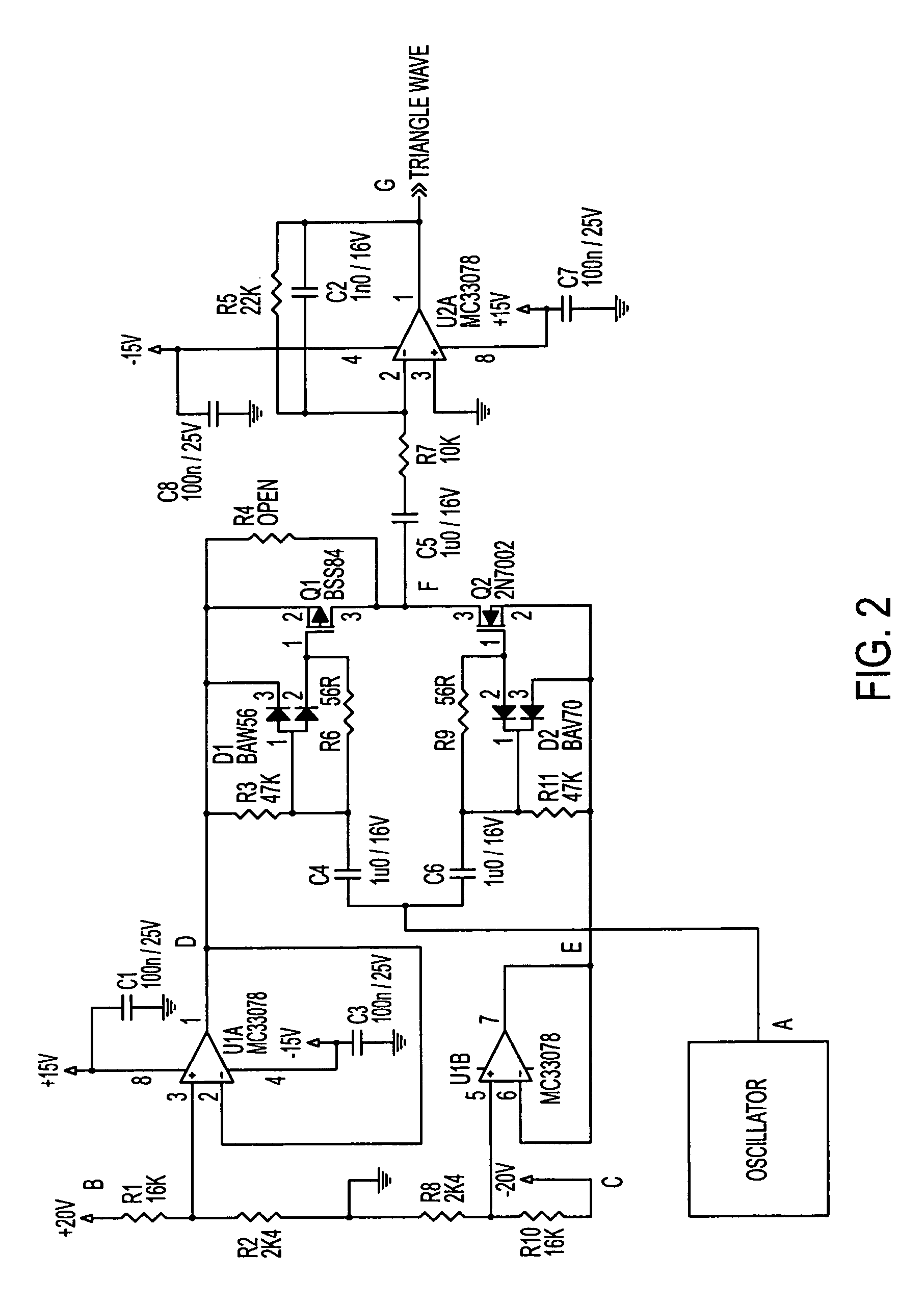

Image

  • Power supply rejection for pulse width modulated amplifiers and automatic gain control
  • Power supply rejection for pulse width modulated amplifiers and automatic gain control
  • Power supply rejection for pulse width modulated amplifiers and automatic gain control

Examples


Embodiment Construction

[0022]Reference will now be made in detail to the preferred embodiments of the present invention, examples of which are illustrated in the accompanying drawings.

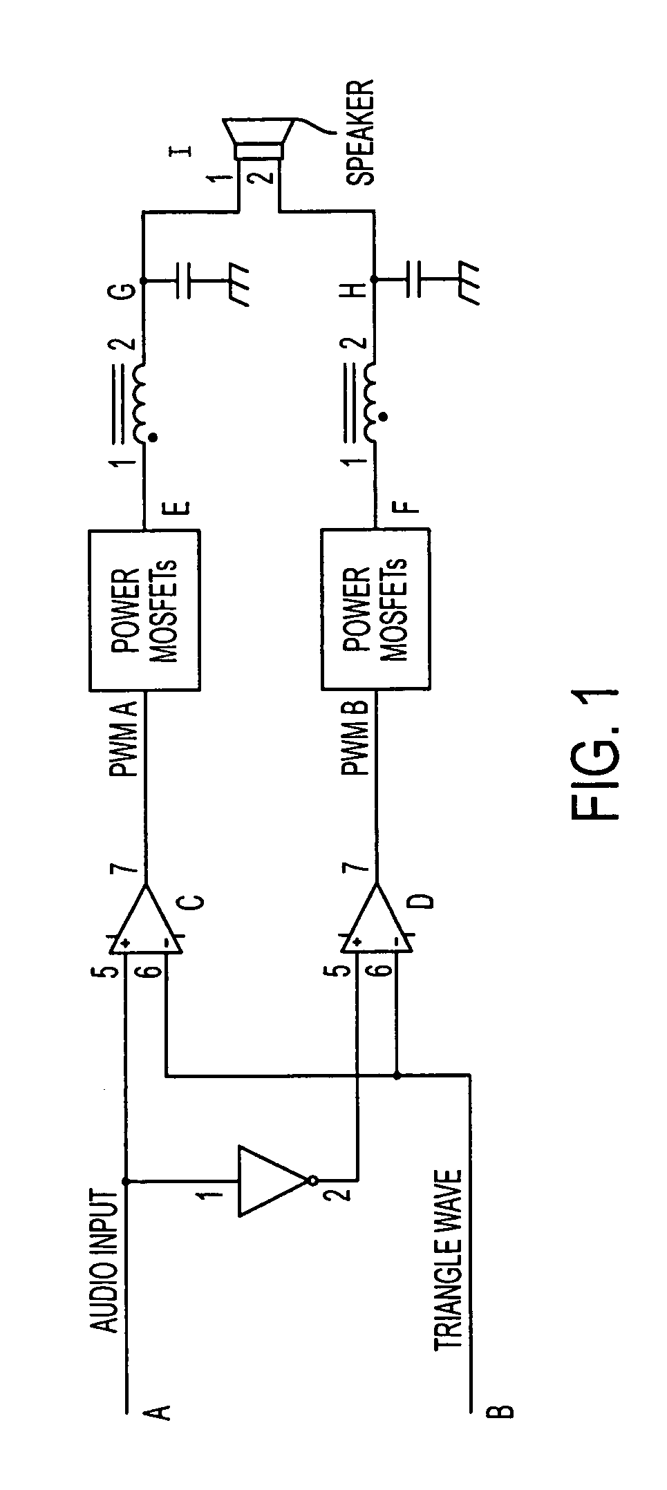
[0023]With reference to FIG. 1, in the basic operation of a class D amplifier, an audio input signal (A) goes into a first comparator (C). The audio input signal is also inverted and then goes into a second comparator (D). A triangle wave (B) is input into both comparators. Within both comparators (C, D), the audio input signal is compared to the triangle wave. If the audio input signal is higher than the triangle wave, then the comparator output is high. If the audio input signal is lower than the triangle wave, then the comparator output is low. The comparators output pulse width modulated (“PWM”) signals (PWM A, PWM B) that correlate to the audio input signal. The PWM signal is rectified in the power Metal-Oxide Semiconductor Field-Effect Transistors (“MOSFETs”), which have a PWM output that switches between the + / − volta...


PUM


Abstract

A circuit according to the present invention improves the power supply rejection ratio for a pulse width modulated digital amplifier and can be used as a compressor and / or limiter. The circuit preferably operates by using voltage level translation to vary the amplitude of a triangle wave in response to changes in power supply voltage prior to input of the wave into a comparator of the PWM device. Because the circuit operates to improve power supply rejection, little or no distortion is introduced into the signal when used as a compressor and / or limiter. Additionally, the circuit is optionally implemented in a Class D amplifier, and provides a lower cost of implementation than conventional designs in such implementations.

Description

CROSS-REFERENCE TO RELATED APPLICATIONS[0001]This application claims priority to U.S. Provisional Patent Application Ser. No. 60 / 535,134, filed Jan. 7, 2004, which is hereby incorporated by reference in its entirety.[0002]This application includes material which is subject to copyright protection. The copyright owner has no objection to the facsimile reproduction by anyone of the patent disclosure, as it appears in the Patent and Trademark Office files or records, but otherwise reserves all copyright rights whatsoever.BACKGROUND OF THE INVENTION[0003]Class D amplifiers differ from conventional power amplifiers, such as Class A and Class B power amplifiers, in various respects. Conventional power amplifiers have an output voltage or current that is proportionally larger than its input. The output devices operate in the linear region, where the device is partially “on”. As a result, much of the power that is supplied to the amplifier converts to heat and is not efficiently utilized. L...

Claims


Application Information

Patent Timeline
Patent Type & Authority Patents(United States)
IPC IPC(8): H03F3/217H03F1/30H03F1/32H03G7/00
CPCH03F1/30H03F1/32H03F3/217H03F3/2173H03G7/00H03F2200/351H03F2200/471H03F2200/78
Inventor ZEPP, DAVID
Owner ALTEC LANSING LLC
Learn More