
High-order temperature compensation complementary superposition-based high-precision band-gap reference circuit

A high-order temperature compensation and reference circuit technology, applied in the direction of adjusting electrical variables, control/regulation systems, instruments, etc., can solve problems such as increased process sensitivity, increased impact on circuit performance, and increased difficulty, achieving high process stability sexual effect

Inactive Publication Date: 2011-05-25
SOUTHEAST UNIV
View PDF4 Cites 9 Cited by
  • Summary
  • Abstract
  • Description
  • Claims
  • Application Information

AI Technical Summary

Problems solved by technology

[0004] In the temperature range of -40°C to 125°C, the temperature coefficient of the existing classical linear compensation bandgap voltage base can theoretically be reduced to less than 10ppm / °C. On this basis, various types of high-order compensation based on the principle of piecewise nonlinear compensation For the benchmark structure, its temperature coefficient can be reduced to 3-5ppm / ℃. If the temperature coefficient continues to be reduced, not only the difficulty will increase obviously, but also the process sensitivity will increase with the decrease of the temperature coefficient, and the impact of process drift on circuit performance will increase. Difficulty of Baseline Adjustment
When the performance of the reference temperature coefficient after the maximum process drift is degraded to be worse than the temperature characteristics of the corresponding first-order linear compensation reference, the practical value of the reference high-order compensation structure is difficult to reflect

Method used


Image

  • High-order temperature compensation complementary superposition-based high-precision band-gap reference circuit
  • High-order temperature compensation complementary superposition-based high-precision band-gap reference circuit
  • High-order temperature compensation complementary superposition-based high-precision band-gap reference circuit

Examples


Embodiment Construction

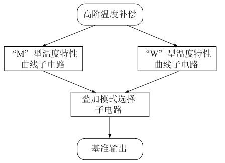
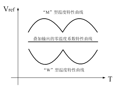
[0016] Such as figure 1 As shown, the present invention is based on a high-precision bandgap reference circuit based on high-order temperature compensation complementary superposition, including "M" type and "W" type temperature characteristic curve subcircuits and superposition mode selection subcircuits, "M" type and "W" type The temperature characteristic curve sub-circuits are complementary and symmetrical, and the "M" and "W" temperature characteristic curve sub-circuits include a feedback control circuit, a current generation circuit and an output circuit. The input end of the sub-circuit and the output end of the output circuit are connected in series with the feedback control circuit and then connected with the input end of the current generation circuit.

[0017] Such as image 3 As shown, the circuit of the present invention includes two sub-circuits for generating complementary temperature characteristic curves and one sub-circuit for superposition selection mode. ...


PUM


Abstract

The invention discloses a high-order temperature compensation complementary superposition-based high-precision band-gap reference circuit. The circuit comprises an M-type temperature characteristic curve sub-circuit, a W-type temperature characteristic curve sub-circuit and a superposition mode selection sub-circuit, wherein the M-type temperature characteristic curve sub-circuit and the W-type temperature characteristic curve sub-circuit are arranged complementarily and symmetrically; both the M-type temperature characteristic curve sub-circuit and the W-type temperature characteristic curve sub-circuit comprise a feedback control circuit, a current generating circuit and an output circuit, wherein the current generating circuit is connected with the input end of the superposition mode selecting sub-circuit after being connected with an output circuit in series; and the output end of the output circuit is connected with the input end of the current generating circuit after being connected with the feedback control circuit in series. The circuit reduces a temperature coefficient of an output reference voltage to the maximum by using a nonlinear temperature compensation structure and a nonlinear temperature compensation method, thereby meeting the application of a high-precision system.

Description

technical field [0001] The invention relates to a composite high-order temperature-compensated bandgap reference circuit, which belongs to the technical field of analog circuits, and specifically relates to the generation of a two-order nonlinear temperature compensation reference, the adjustment of temperature characteristic curves, and the superposition or selection control of reference voltages. Background technique [0002] The reference voltage is similar to but different from the stabilized voltage source. The common point of both is that they can provide stable voltage. The reference voltage usually has no load driving capability and can only drive capacitive loads, but it has extremely high requirements on voltage stability, mainly including temperature stability and power supply stability. As the name suggests, the stabilized voltage source is a stable voltage source with strong load driving capability, so more attention should be paid to the output stability under ...

Claims


Application Information

Patent Timeline
Patent Type & Authority Applications(China)
IPC IPC(8): G05F3/30
Inventor 吴金李浩渠宁龙寅
Owner SOUTHEAST UNIV
Learn More