LED power supply device

a power supply device and power supply circuit technology, applied in the direction of electric variable regulation, process and machine control, instruments, etc., can solve the problems of inability to achieve the desired effect of reducing the cost, reducing the cost, and reducing the cost of the devi

Inactive Publication Date: 2006-11-14
TOYODA GOSEI CO LTD
View PDF11 Cites 21 Cited by
  • Summary
  • Abstract
  • Description
  • Claims
  • Application Information

AI Technical Summary

Benefits of technology

[0019]According to the power supply device configured in this manner, since the oscillating loop circuit is formed by the essential circuit to operate the LED power supply device comprising the switching circuit, LED and comparison circuit, no independent oscillation circuit such as a triangular wave oscillator is required. Thus, the low-cost device can be realized.
[0020]According to another aspect of the invention, the reference voltage generation circuit generates the reference voltage by a voltage drop caused by a diode and a resistor. In comparison with the bandgap reference type reference voltage generation circuit, such a circuit is simple in configuration and its cost can be substantially reduced. According to the simple reference voltage generation circuit of the invention, the precision of the reference voltage obtained cannot be high. As a result, current applied to the LED varies, but the variation of the current cannot be practically detrimental to the LED emitting light with high brightness.
[0021]According to the present invention, since the error amplifier of FIG. 1 can be omitted, the low-cost device can be realized.
[0022]According to the present invention, by setting the reference voltage to be low compared with the versatile power supply circuit of FIG. 1, feedback voltage from the LED can be low, and power loss can be reduced.
[0026]The switching circuit and the comparison circuit may be versatile. In the embodiment, these are configured by transistors so that cost reduction is ensured.

Problems solved by technology

However, as LED brightness is required to be higher so that the conducting current is a few hundreds of milliamperes, heat released and power consumed by the resistor are innegligible.
In addition, since resistor size is larger, and design for heat releasing on a substrate side is required, constraints on design in portions other than the power supply circuit of the LED are caused.
It has unnecessary functions for LED lighting control.
This is because even if current applied to the LED is changed by about ±20% in a high-brightness region, the human eye cannot recognize its change.
As a result, power consumption due to feedback loss is innegligible.
However, such ICs are costly because they use high-speed switching device for miniaturization, or specialized circuit configuration for high efficiency.

Method used


Image

  • LED power supply device
  • LED power supply device
  • LED power supply device

Examples


Embodiment Construction

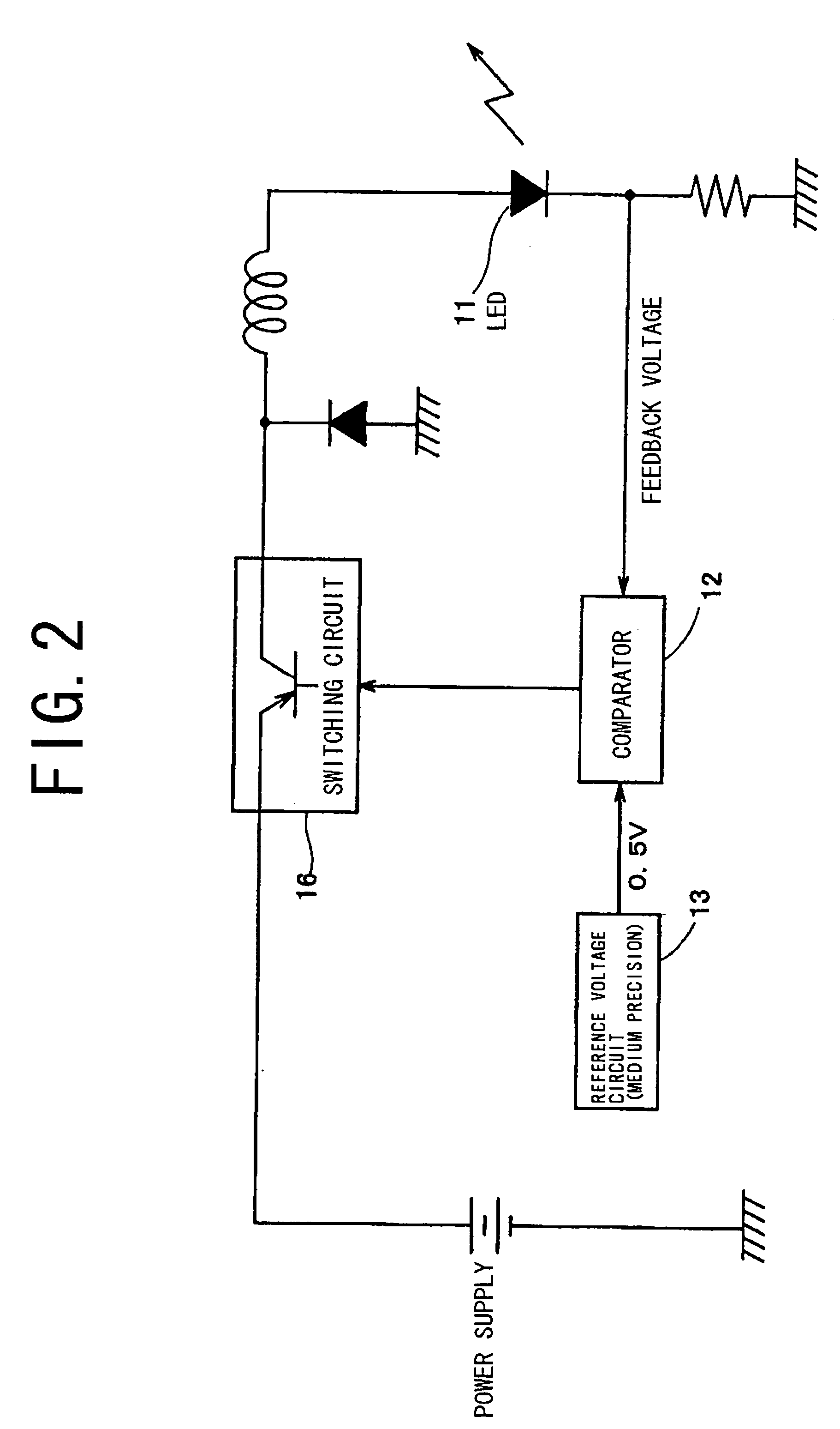
[0038]FIG. 2 is a block diagram showing a configuration of a power supply device according to an embodiment of the invention. FIG. 3 is a circuit diagram of the power supply device of FIG. 2.

[0039]As apparent from FIG. 2, in the power supply device of the embodiment, feedback voltage from an LED 11 is input to a comparator 12, and compared with reference voltage (about 0.5V) from reference voltage generation circuit 13. A result (control voltage) compared is input to switching circuit 16 to control its turn-on / off. A loop circuit is formed by the switching circuit 16, LED 11 and comparator 12. By turning on / off the switching circuit 16 in response to the control voltage from the comparator 12, the loop circuit oscillates, and current input to the LED 11 is thereby maintained substantially constant.

[0040]According to the power supply device of the embodiment configured in this manner, since the oscillating loop circuit is formed by the essential circuit to operate the LED power suppl...


PUM


Abstract

An LED power supply device has a loop circuit formed by a switching circuit, an LED and a comparison circuit, and a reference voltage generation circuit for providing reference voltage to the comparison circuit. The loop circuit oscillates so that substantially constant current is applied to the LED.

Description

[0001]The present application is based on Japanese patent application No.2003-305770, the entire contents of which are incorporated herein by reference.BACKGROUND OF THE INVENTION[0002]1. Field of the Invention[0003]The present invention relates to an LED power supply device. The power supply device of this invention is suitable for in-vehicle use.[0004]2. Description of the Related Art[0005]In an LED power supply device whose conducting current is a few tens of milliamperes, current applied is controlled by connecting a resistor in series with the LED. However, as LED brightness is required to be higher so that the conducting current is a few hundreds of milliamperes, heat released and power consumed by the resistor are innegligible. In addition, since resistor size is larger, and design for heat releasing on a substrate side is required, constraints on design in portions other than the power supply circuit of the LED are caused.[0006]Such resistor constraints can be overcome by us...

Claims


Application Information

Patent Timeline
Patent Type & Authority Patents(United States)
IPC IPC(8): G05F1/00H01L33/00H05B37/02H02M3/155H05B44/00
CPCH05B33/0815H05B45/375H05B45/38
Inventor TANABE, TETSUO
Owner TOYODA GOSEI CO LTD
Why Eureka
Try Eureka