
Magnetic recording disk drive with patterned media and compensation for write-clock timing error caused by rotational disturbances

a magnetic recording and disk drive technology, applied in digital recording, nanoinformatics, instruments, etc., can solve the problems of small speed variation, error of reference clock signal, and rotational speed of disk driv

Inactive Publication Date: 2006-11-07
WESTERN DIGITAL TECH INC
View PDF13 Cites 32 Cited by
  • Summary
  • Abstract
  • Description
  • Claims
  • Application Information

AI Technical Summary

Benefits of technology

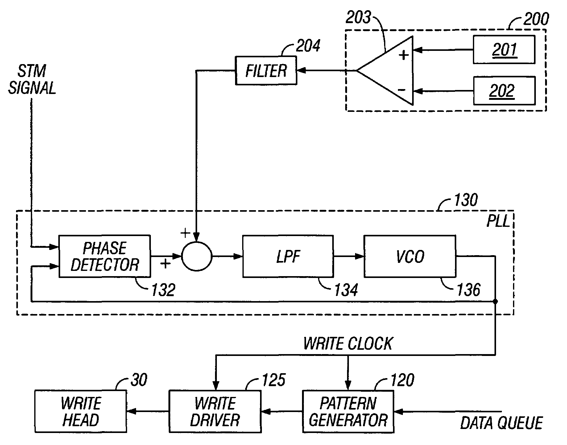
The invention is a magnetic recording disk drive with a patterned magnetic recording disk and a write-clock-generation circuit for timing write pulses. The drive also includes a rotational vibration sensor that adjusts the timing of the write pulses to correct for errors caused by rotational disturbances. The write-clock-generation circuit may be a phase-locked-loop (PLL) circuit with a voltage-controlled-oscillator (VCO) that receives a reference clock signal synchronized to disk rotation and multiplies it to generate a higher-frequency write-clock signal. The rotational vibration sensor may be a rotational accelerometer that detects disk drive disturbances that affect the speed of the spindle motor, causing errors to the reference clock signal input to the write-clock-generation circuit and thus in errors in the timing of the write-clock signal. The invention compensates for the write-clock timing error caused by rotational disturbances by using the angular acceleration signal from the rotational accelerometer.

Problems solved by technology

These disturbances affect the speed of the spindle motor, causing small speed variations or “jitter”, and thus the rotational speed of the disk.
This results in errors to the reference clock signal input to the write-clock-generation circuit and thus in errors in the timing of the write-clock signal.

Method used


Image

  • Magnetic recording disk drive with patterned media and compensation for write-clock timing error caused by rotational disturbances
  • Magnetic recording disk drive with patterned media and compensation for write-clock timing error caused by rotational disturbances
  • Magnetic recording disk drive with patterned media and compensation for write-clock timing error caused by rotational disturbances

Examples


Embodiment Construction

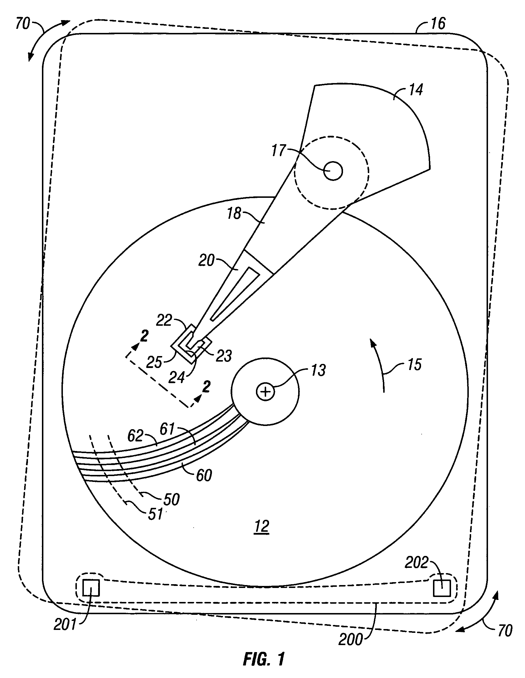
[0017]FIG. 1 is a block diagram of a magnetic recording hard disk drive according to the present invention. The disk drive includes a magnetic recording disk 12 that is rotated about an axis of rotation 13 in direction 15 by a spindle motor (not shown) mounted to the disk drive housing or base 16. The disk 12 has a magnetic recording layer patterned into magnetizable blocks that define concentric data tracks, such as typical tracks 50, 51, and servo sectors, such as typical servo sectors 60, 61, 62. The servo sectors extend generally radially across the concentric data tracks so that each data track has a plurality of equally-angularly spaced servo sectors that extend around the track. Each of the servo sectors in a data track contains a servo timing mark (STM), also called a servo address mark (SAM), that indicates the start of the servo sector, and servo positioning information.

[0018]The disk drive also includes a rotary voice coil motor (VCM) actuator 14 supported on the base 16....


PUM

PropertyMeasurementUnit
phaseaaaaaaaaaa
data densityaaaaaaaaaa
magnetic domainaaaaaaaaaa

Abstract

A magnetic recording disk drive has a patterned magnetic recording disk with data blocks of magnetizable material separated by nonmagnetic regions, a write-clock-generation circuit for timing write pulses to the write head, and a rotational vibration sensor that adjusts the timing of the write pulses to correct for errors caused by rotational disturbances to the disk drive. The write-clock-generation circuit receives a reference clock signal synchronized to disk rotation and multiplies it to generate a higher-frequency write-clock signal. The write-clock-generation circuit includes a phase detector that compares the phase of the reference clock signal and the write-clock signal and provides an error signal. The output of the rotational vibration sensor is summed with the phase detector error signal to compensate for disk rotation speed changes caused by rotational disturbances.

Description

BACKGROUND OF THE INVENTION[0001]1. Field of the Invention[0002]This invention relates generally to magnetic recording disk drives for use with patterned media, wherein each data bit is stored in a magnetically isolated block on the disk, and more particularly to such a disk drive with an improved clock for writing the data.[0003]2. Description of the Related Art[0004]Magnetic recording hard disk drives with patterned magnetic recording media have been proposed to increase the data density. In patterned media, the magnetic material on the disk is patterned into small isolated blocks or islands such that there is a single magnetic domain in each island or “bit”. The single magnetic domains can be a single grain or consist of a few strongly coupled grains that switch magnetic states in concert as a single magnetic volume. This is in contrast to conventional continuous media wherein a single “bit” may have multiple magnetic domains separated by domain walls. To produce the required mag...

Claims


Application Information

Patent Timeline
Patent Type & Authority Patents(United States)
IPC IPC(8): G11B5/09
CPCB82Y10/00G11B5/59627G11B20/10G11B27/30G11B5/59616G11B5/746G11B2220/20
Inventor SEMBA, TETSUO
Owner WESTERN DIGITAL TECH INC
Learn More