
Optical system design for a universal computing device

a computing device and optical system technology, applied in the direction of static indicating devices, instruments, lenses, etc., can solve the problems of device tie-in, prohibitively expensive first wave of computers, and cost effective use in business settings, so as to improve performance and handling perspective, the effect of low resolution

Inactive Publication Date: 2006-11-07
MICROSOFT TECH LICENSING LLC
View PDF42 Cites 98 Cited by
  • Summary
  • Abstract
  • Description
  • Claims
  • Application Information

AI Technical Summary

Benefits of technology

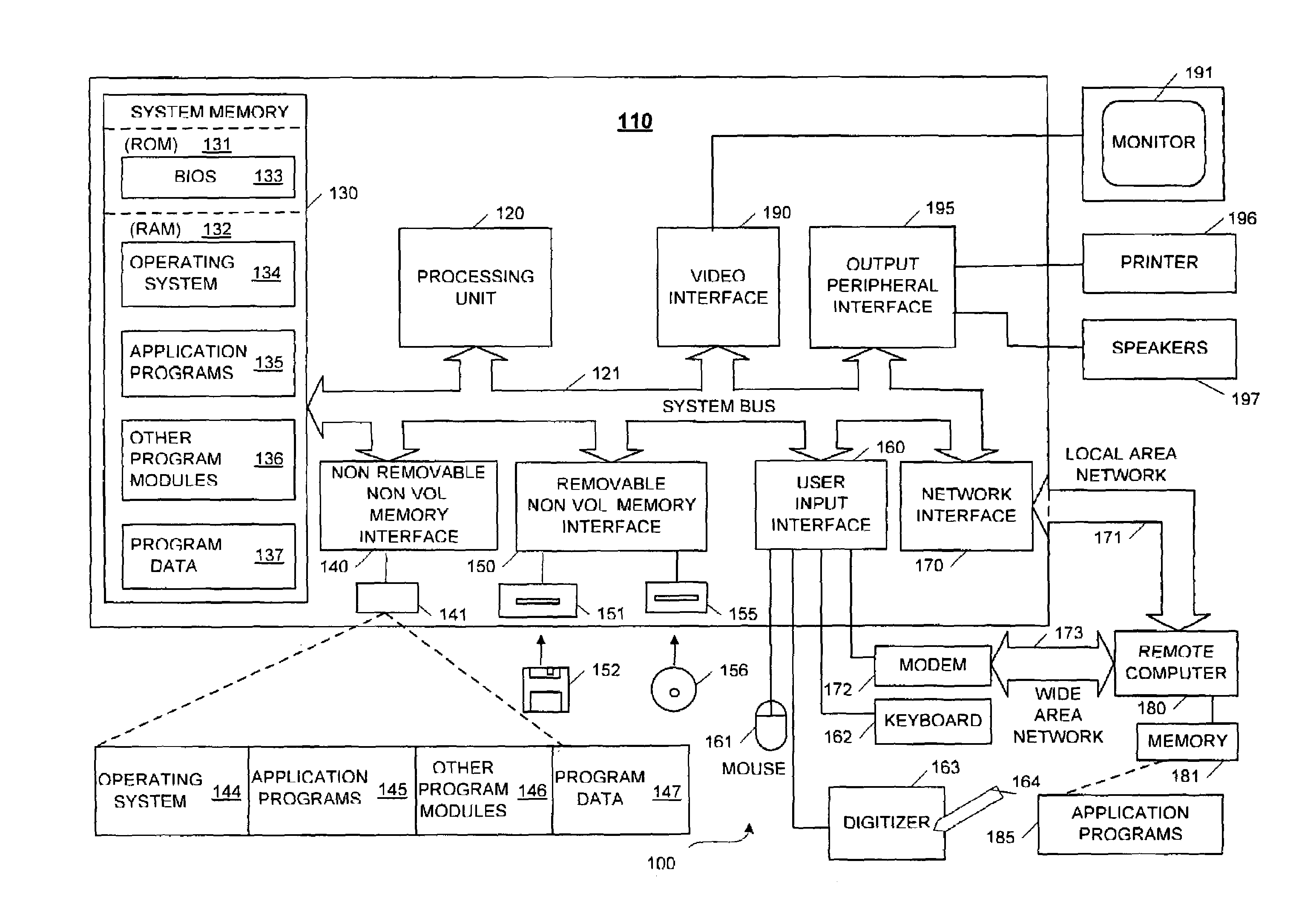
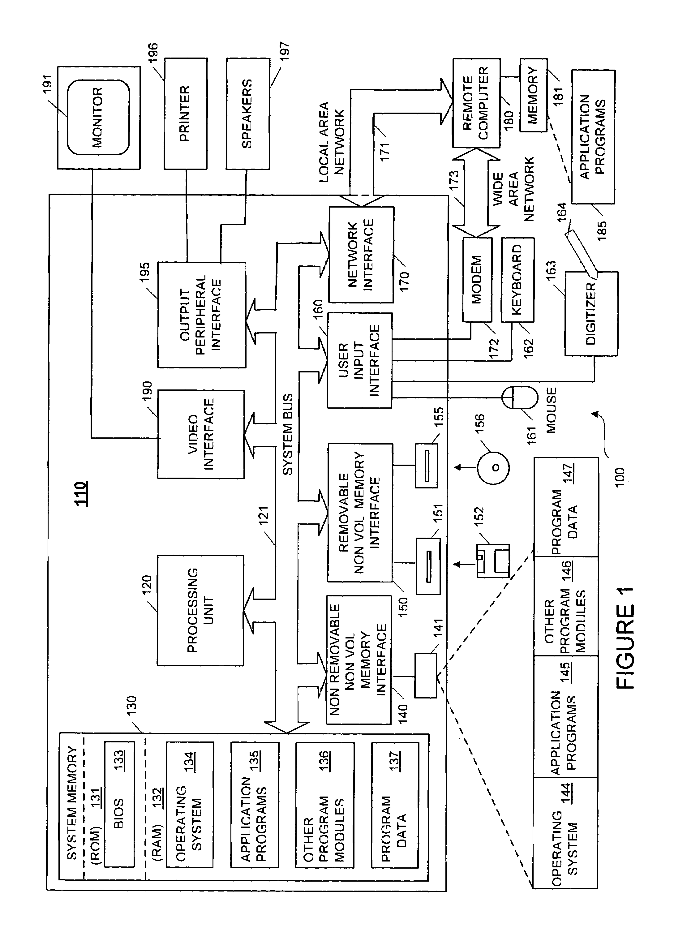
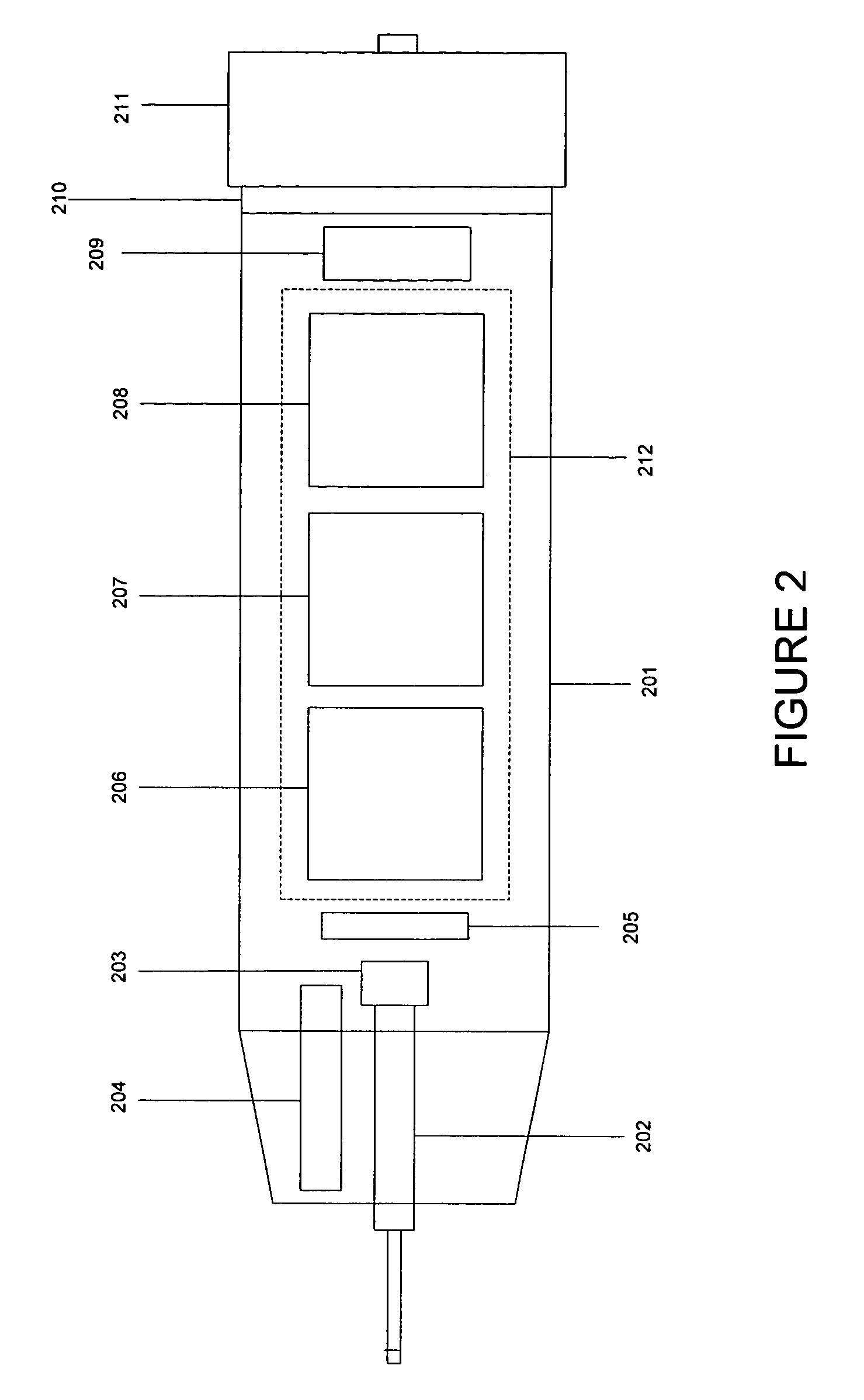
The present invention provides a common user interface for users across divergent computing platforms. It introduces an input device that can generate electronic ink and other inputs independently of the device for which the data is intended. The input device may be a portable computing device that can be identified by a specific identification for multiple users to operate on a document or application program simultaneously. The invention uses infrared lighting and maze patterns printed on a surface to capture the position of the input device. An off-set optical system with infrared illumination is used to detect the positional encoding which may be covered by existing document content or ink under visible light illumination. The technical effects of the invention include improved performance and handling perspective, as well as detection of positional encoding for more efficient input device usage.

Problems solved by technology

The first wave of computers was prohibitively expensive, and was only cost effective for use in business settings.
A drawback associated with the use of a stylus is that such devices are tied to the computing device containing the sensor board.
Prior portable computing devices may lack a specific form of identification for multiple user configurations.
As such, if two such portable computing devices operated simultaneously, a host computer becomes confused and senses the annotations to be from the same computing device.
Without an ability to identify the computing device from which an annotation occurs, a host PC cannot track changes specifically to a particular computing device.
Prior portable computing devices may lack the ability to track writing that a user may perform on top of existing ink.
Prior computing devices may track writing of a user on clean, ink free surfaces; however, the image capturing capabilities of these devices cannot track writing that occurs on existing ink.
Further, prior portable computing devices may lack the ability to handle perspective that naturally exists when a writing implement, such as a pen, is held.
However, most individuals do not hold a pen at a 90 degree angle to a surface.
As such, perspective becomes a problem for the sensor to adequately compensate for the angle of the computing device.

Method used


Image

  • Optical system design for a universal computing device
  • Optical system design for a universal computing device
  • Optical system design for a universal computing device

Examples


Embodiment Construction

[0032]Aspects of the present invention relate to an input device that may be used in a variety of different platforms from controlling a desktop or laptop computer, writing on a whiteboard, writing on a surface, such as paper, controlling a PDA or cellular phone, or creating ink that may be ported among various platforms.

Terms

[0033]Pen—any writing implement that may or may not include the ability to store ink. In some examples a stylus with no ink capability may be used as a pen in accordance with embodiments of the present invention.

[0034]Camera—an image capture system.

[0035]Active Coding—incorporation of codes within the object or surface over which the input device is positioned for the purpose of determining positioning and / or movement of the input device using appropriate processing algorithms.

[0036]Passive Coding—detecting movement / positioning of the input device using image data, other than codes incorporated for that purpose, obtained from the object or surfaces over which t...


PUM


Abstract

The universal input device provides a common user interface for a variety of different computing platforms including printed documents. Using the present system, one may use the universal input device to control various computing devices as well as capture handwritten electronic ink and have the electronic ink be associated with new or stored documents. The universal input device can be identified by a specific identification in order to allow for multiple users to operate on a document and / or within an application program simultaneously or not. An off-set optical system with infrared illumination handles perspective and helps detect positional encoding which can be covered by existing ink under common visible light illumination.

Description

[0001]This application is a continuation in part of U.S. patent application Ser. No. 10 / 284,417 filed Oct. 31, 2002, entitled “Universal Computing Device,” the contents of which are herein incorporated by reference.FIELD OF THE INVENTION[0002]Aspects of the present invention are directed generally to a computer input device for generating smooth electronic ink. More particularly, aspects of the present invention are directed to an input device that may be used on divergent platforms, while providing a common user interface.BACKGROUND OF THE INVENTION[0003]Computing systems have dramatically changed the way in which we live. The first wave of computers was prohibitively expensive, and was only cost effective for use in business settings. As computers became more affordable, the use of personal computers both in the workplace and at home have become so widespread that computers have become as common as desks in the office and kitchen tables in the home. Microprocessors have been incor...

Claims


Application Information

Patent Timeline
Patent Type & Authority Patents(United States)
IPC IPC(8): G09G5/00G06F3/041G02B3/00G02B7/00G02B9/00G02B11/00G02B13/00G02B15/00G02B17/00G02B25/00G06F3/02G06F3/03G06F3/033G06F3/042G06F19/00G06K7/00G06K9/22G06T1/00G06T11/80G11C13/00H04N1/107
CPCG06F3/03545G06F3/0317G06F3/0321G06K7/00
Inventor WANG, JIANZHANG, CHUNHUI
Owner MICROSOFT TECH LICENSING LLC
Learn More