
Dynamic beamforming for ad hoc networks

a beamforming and dynamic technology, applied in diversity/multi-antenna systems, antennas, site diversity, etc., can solve the problems of antenna gain and null antenna pattern, energy to be transmitted in wrong directions as well as the right direction, and high amount of interference signals

Active Publication Date: 2006-10-31
VERIZON PATENT & LICENSING INC +1
View PDF4 Cites 10 Cited by
  • Summary
  • Abstract
  • Description
  • Claims
  • Application Information

AI Technical Summary

Problems solved by technology

Even when a location of a remote communication device is known, however, transmissions to the remote device via an omni-directional antenna can cause energy to be transmitted in wrong directions as well as the right direction.
Similarly, when receiving transmissions from a remote device via an omnidirectional antenna, signals from the remote device may be received, as well as interfering signals from devices in different locations around the omnidirectional antenna.
The amount of interfering signals may be high, especially if transmitting devices also use omnidirectional antennas.
Given different gains and / or phases applied to each array element (weights), arbitrary constructive and destructive propagation patterns can effectively be created, thereby causing antenna patterns of gains and nulls.
This is a difficult task in a wireless network, such as an ad hoc network in which all nodes are moving and signals may be received from any direction at any time.

Method used


Image

  • Dynamic beamforming for ad hoc networks
  • Dynamic beamforming for ad hoc networks
  • Dynamic beamforming for ad hoc networks

Examples


Embodiment Construction

[0019]The following detailed description of the invention refers to the accompanying drawings. The same reference numbers in different drawings may identify the same or similar elements. The following detailed description does not limit the invention. Instead, the scope of the invention is defined by the appended claims and equivalents.

Operating Environment

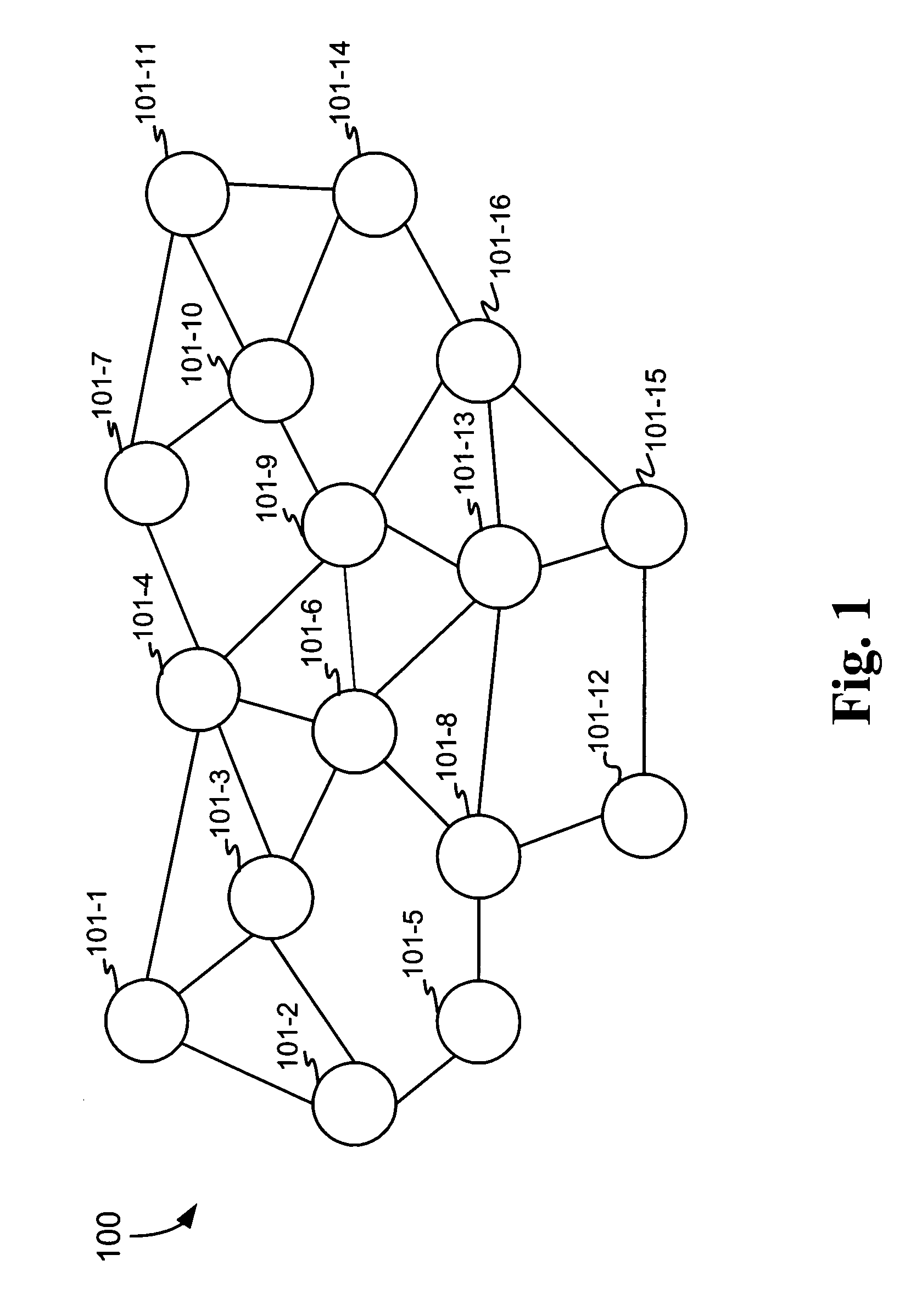
[0020]One type of wireless network is an “ad-hoc” network. In an ad-hoc network, nodes may cooperatively route traffic among themselves. Network nodes in these networks may not be permanent: they are, instead, based on whether signals can be adequately decoded between two nodes. The network may adjust dynamically to changing node conditions, which may result from node mobility or failure.

[0021]In general, some or all of the nodes in an ad-hoc network are capable of network routing functions (“routers”), while other nodes may be merely source or destinations for data traffic (“endpoints”). All nodes in the network may execute a set...


PUM


Abstract

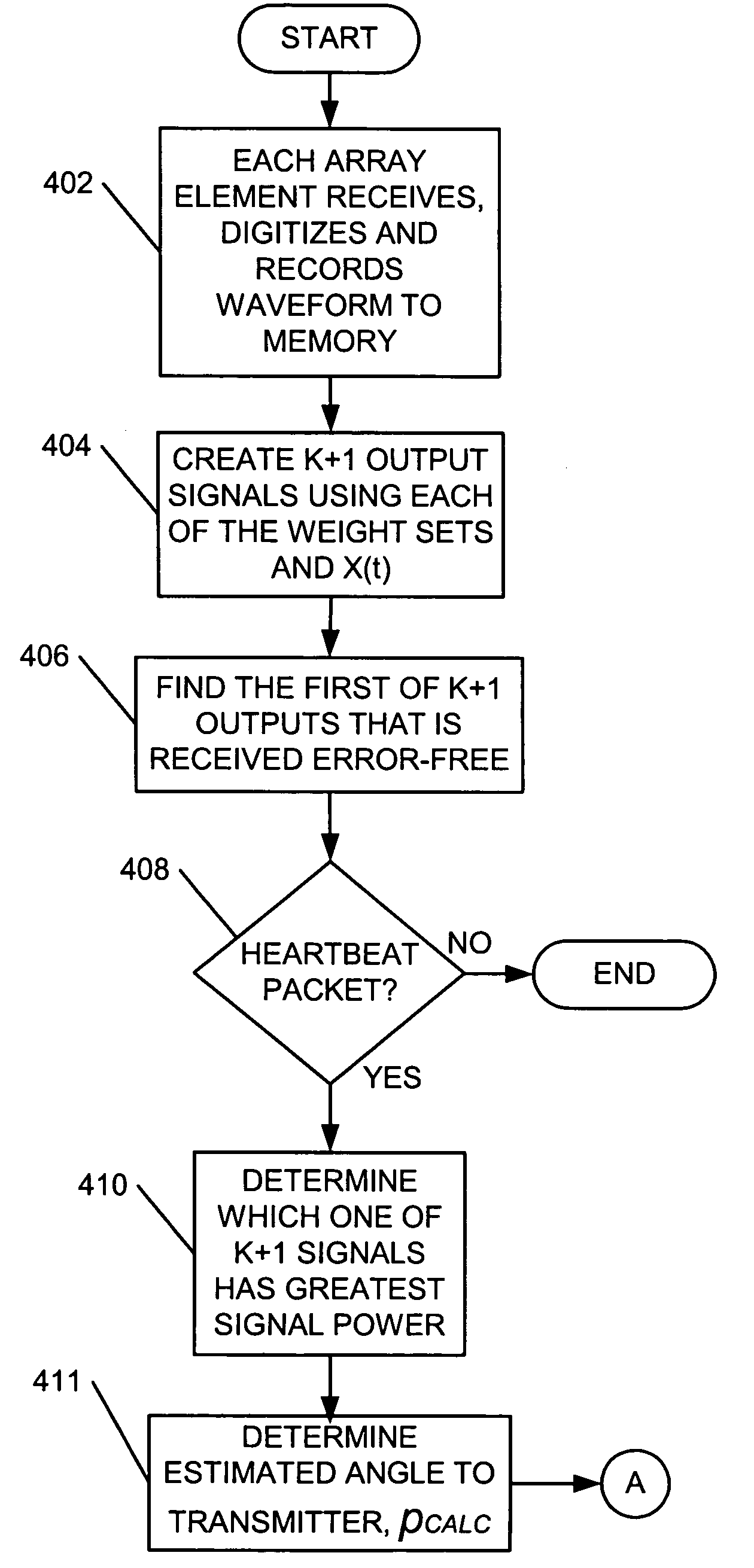
A method, a node and a machine-readable medium are provided for dynamically adjusting a beam of an adaptive antenna array (302). A receiving node (101) receives, via a group of antenna array elements (302), a signal from a transmitting node (101). Each received signal from the antenna array elements (101) is digitized and recorded. K+1 output signals are generated from the recorded digitized signal. The k+1 output signals are generated by applying each of a group of weight sets to the recorded digitized signal. Each of the weight sets corresponds to a different one of k known neighboring nodes (101) and a weight set for generating an omnidirectional propagation pattern. Which one of the k+1 output signals to process is determined. The determined one of the k+1 output signals is processed and the packet encoded in the determined one of the k+1 output signals is decoded.

Description

TECHNICAL FIELD[0001]Implementations consistent with the principles of the invention, relate to the field of wireless communications and, more particularly, to systems and methods for using adaptive antenna arrays to perform dynamic beamforming in wireless networks.BACKGROUND OF THE INVENTION[0002]Omnidirectional antennas can detect and generate signals equally well in all directions. Even when a location of a remote communication device is known, however, transmissions to the remote device via an omni-directional antenna can cause energy to be transmitted in wrong directions as well as the right direction. Similarly, when receiving transmissions from a remote device via an omnidirectional antenna, signals from the remote device may be received, as well as interfering signals from devices in different locations around the omnidirectional antenna. The amount of interfering signals may be high, especially if transmitting devices also use omnidirectional antennas.[0003]A switched beam ...

Claims


Application Information

Patent Timeline
IPC IPC(8): H04B7/00H01Q3/00
CPCH01Q25/00H04B7/022H04B7/0617
Inventor REDI, JASON KEITHKOLEK, STEPHEN R.
Owner VERIZON PATENT & LICENSING INC
Learn More