
Mouthguard

a mouthguard and rubber band technology, applied in the field of mouthguards, to achieve the effect of enhancing the ability of mouthguards, enhancing the protection of mouthguards, and maintaining flexibility

Inactive Publication Date: 2006-10-31
TOTAL GARD CORP
View PDF61 Cites 16 Cited by
  • Summary
  • Abstract
  • Description
  • Claims
  • Application Information

AI Technical Summary

Benefits of technology

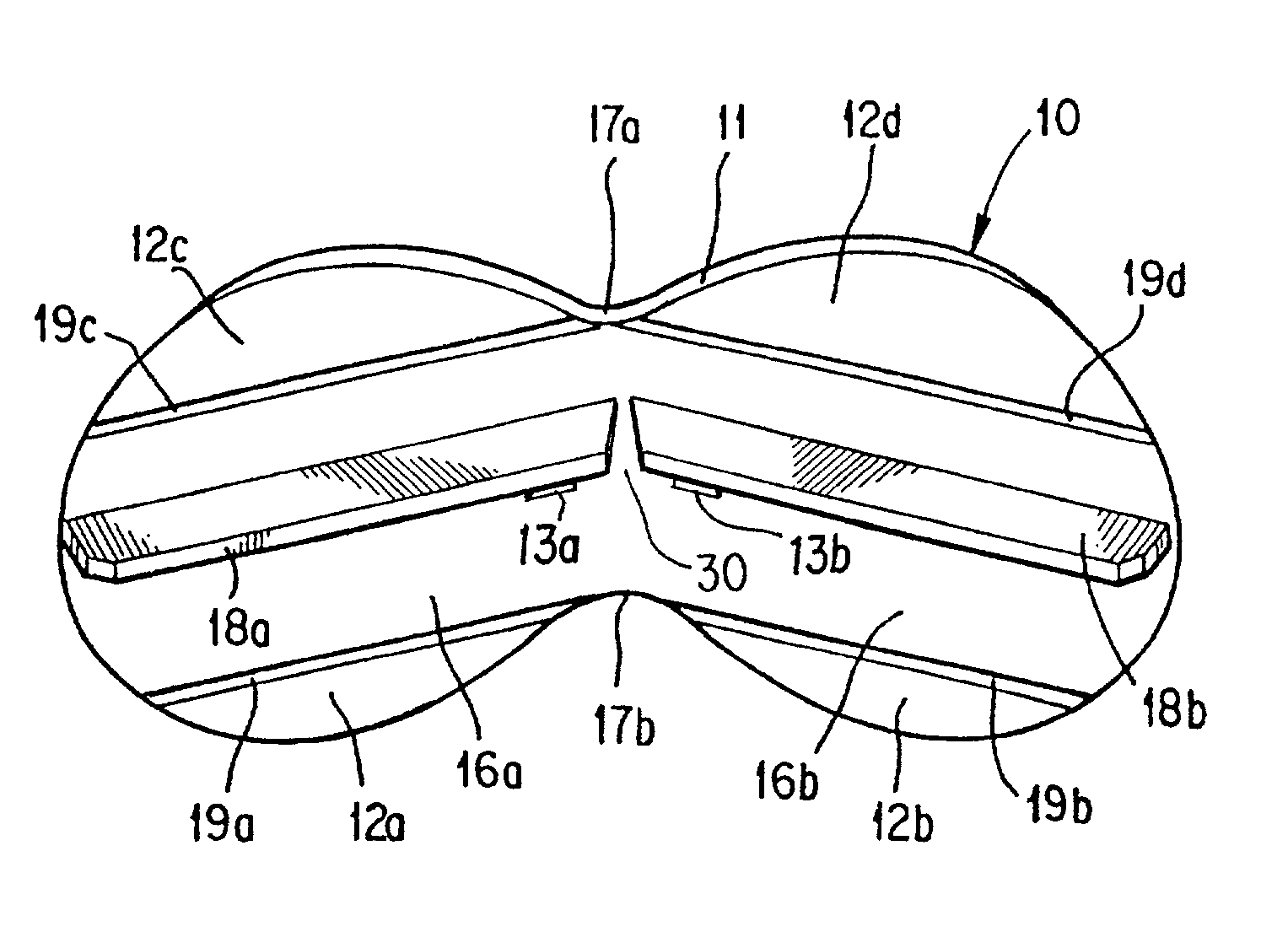
[0006]This invention meets the above need, while avoiding the disadvantages and drawbacks of the prior art by providing a mouthguard that is simple, comfortable, and protects the teeth including some or all of the anterior teeth without inducing gagging. The invention includes a bite tab that provides added protection to the front teeth—it provides increased protection from trauma and helps prevent the teeth from grinding together. A stress-breaking split may be inserted in the anterior portion of the bite tab to help maintain its flexibility. The split may enhance the mouthguard's ability to adapt to any arch width size so that no adjustments such as boiling or trimming are required. Thus, no time consuming preparations are needed prior to using the mouthguard—it is ready to wear. The mouthguard of the invention thus provides protection to the teeth, lips, gums, and TMJ while helping to eliminate the gagging caused by other mouthguards. It provides these safety features, and at the same time is convenient, simple to use, and inexpensive.
[0008]According to another aspect of the invention, a mouthguard may have a frame member adapted to fit into the mouth of a wearer, wherein the frame member has an outwardly facing front surface, an inwardly facing rear surface, a central portion and end portions extending from the central portion. A bite tab may be provided that is adapted to engage at least a portion of both the top and bottom teeth of the wearer. The bite tab may extend inwardly from the central portion of the frame and be positioned so to engage at least a portion of the front teeth of the wearer when the jaw of the wearer's mouth is closed. A division separating said bite tab into two sections providing the bite tab with additional flexibility may also be utilized. The division may be an opening that forms a partial split or a complete split, such as a narrow opening, between bite tab sections. Multiple divisions may be provided in the anterior and / or posterior portions of the bite tab sections.

Problems solved by technology

The mouthguard is retained in position by the muscles of the lips and cheeks and protects the teeth of the wearer without inducing gagging—a problem with many other mouthguards.

Method used


Image

  • Mouthguard
  • Mouthguard
  • Mouthguard

Examples


first embodiment

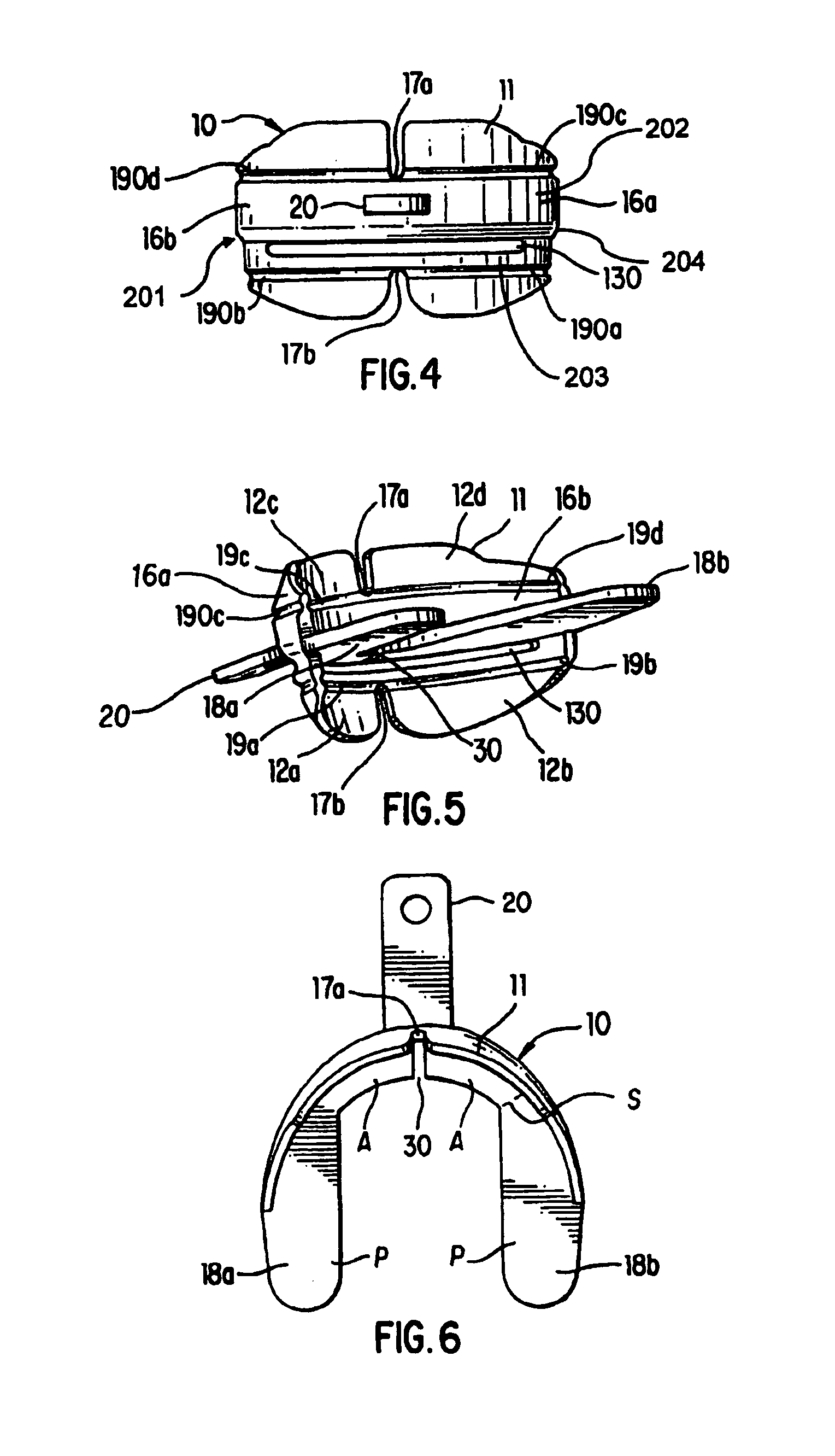
[0023]The mouthguard 10 lays against the outer surface of the teeth which grasp both sides of the inwardly projecting elements 18a and 18b. This provides protection to the temporomandibular joint (TMJ), the anterior teeth, and the posterior teeth against straight-on blows. The curved end members 16a and 16b may have horizontally running flexible grooves (joints), functioning as hinges 19a–d, which allow the muscles in the cheek to press the extensions 12a, 12b, 12c, 12d close to the bone for better retention and comfort. In the first embodiment shown in FIGS. 1–3, flexible grooves 19a–d are provided on the rear surface of end sections 16a and 16b. As shown in FIG. 4, flexible grooves 190a–d can also be placed along the front surface of the curved end sections 16a and 16b to provide the extensions 12a, 12b, 12c, and 12d with added flexibility. Of course, the flexible grooves could be provided solely on the front surface of the mouthguard. With the teeth engaged from both sides of the...

second embodiment

[0024]The lengthwise horizontal grooves 19a, 19b, 19c, 19d (and the grooves 190a–d in the second embodiment) on each side of the posterior extensions provide flexibility particularly during insertion of the mouthguard 10. The flexible mouthguard is also normally in a curved position to permit ease of installation in the user's mouth. If desired, a helmet strap attachment 20 can be molded to the central portion 14 of the outer frame element, as shown schematically in FIG. 1 and in FIG. 4.

[0025]As shown in FIGS. 4–5, the second embodiment contains a third horizontal groove 201 located on the front curved surface of the mouthguard. The groove 201 is defined by a shoulder 204 located just above aperture 130, and below helmet strap attachment 20. In this example, the shoulder 204 is located at about the level of the inwardly projecting elements 18a and 18b. Because of the shoulder 204, the front curved surface 202 of the mouthguard located immediately above the inwardly projecting elemen...


PUM


Abstract

A mouthguard has a flexible frame, and has bite tabs extending from the rear surface of the frame for engaging the wearer's teeth. The bite tabs include anterior bite tabs for engaging the wearer's front teeth. A narrow split may be provided between the anterior bite tabs that allows the bite tabs to maintain their flexibility. The flexible frame lays against the outer surface of the teeth and extends into the buccal folds superiorly and interiorly of the cheek where the muscles hold it in place. Grooves may be positioned lengthwise along the frame above and below the bite tabs for purposes of flexibility and to allow the muscles of the cheek to press the upper and lower extensions of the frame close to the bone for better retention and comfort. The teeth engage the bite tabs, thus preventing the teeth from clashing together and protecting the temporomandibular joint (TMJ). One or more air holes may be provided in the front portion of the mouthguard permit easy breathing. The mouthguard is retained by the muscles of the lips and cheeks, causes no gag reflex, and is simple, comfortable and protective.

Description

BACKGROUND OF THE INVENTION[0001]This invention relates generally to mouthguards and, more particularly to a mouthguard which is retained in position by the muscles of the lips and cheeks and produces no gag reflex. It is designed to fit comfortably over orthodontic appliances or to fit over the teeth naturally without orthodontic appliances of both maxillary and mandibular arches.[0002]The prior art includes U.S. Pat. No. 2,590,118 to Oddo which discloses a mouthpiece having upper and lower channels for the teeth and pivotal front portions of the guard to permit opening of the mouth.[0003]U.S. Pat. No. 4,114,614 to Kesling, discloses a mouthguard appliance comprising a pair of allochiral arch shaped members hingedly connected together and made of a resilient material. The hinge permits folding of the arch shaped members together to retain the members in place on the arches. The teeth contact a plurality of ridges to hold the mouthguard in position.[0004]Various other mouthguards ha...

Claims


Application Information

Patent Timeline
Patent Type & Authority Patents(United States)
IPC IPC(8): A61C5/14A63B71/08
CPCA63B71/085A63B2071/088
Inventor BANCROFT, JAMES J.
Owner TOTAL GARD CORP
Learn More