
Hollow doorframe including electroluminescent illumination system

a technology of electroluminescent illumination and hollow door frame, which is applied in the field of emergency lighting, can solve the problems of obscuring exit indicators, fragile bulbs, and ensuring uniform illumination, and avoiding excessive hea

Inactive Publication Date: 2006-10-24
AADG INC
View PDF18 Cites 27 Cited by
  • Summary
  • Abstract
  • Description
  • Claims
  • Application Information

AI Technical Summary

Benefits of technology

"The present invention is directed to an egress doorframe for illuminating a point of egress, as well as a bypass doorframe for rerouting wiring. The egress doorframe includes frame members with U-shaped channels for mounting electroluminescent strips, while the bypass doorframe includes metal channel raceways for receiving electrical wiring. The lighting system also includes electroluminescent strips within transparent or translucent raceway tube segments that can be attached to structures leading to the egress doorframe. The technical effects of the invention include providing a safe and effective means for illuminating a point of egress, as well as ensuring electrical continuity for the electroluminescent strips on each side of doorways not providing egress."

Problems solved by technology

However, in many structures, the exit indicators may be obscured by smoke or heated air from fire.
However, these conventional illumination technologies require fragile bulbs, and provide for non-uniform illumination and excess heat.
However, the light strips do not interconnect with the EXIT signs located on or about the doorway, nor do they allow for bypassing doorways that are not points of egress.
To date, doorframe manufacturers have not provided any means to accommodate the interconnection of strip lighting on walls and floorboards with the illumination of the egress point, where the illuminators are integral within a doorframe.

Method used


Image

  • Hollow doorframe including electroluminescent illumination system
  • Hollow doorframe including electroluminescent illumination system
  • Hollow doorframe including electroluminescent illumination system

Examples


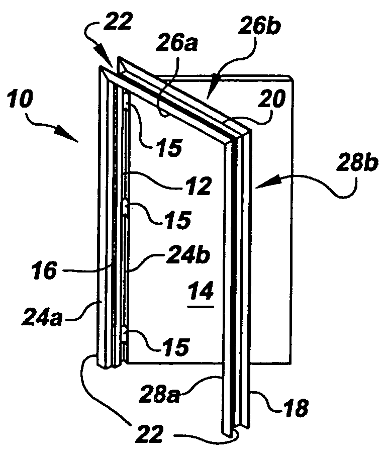
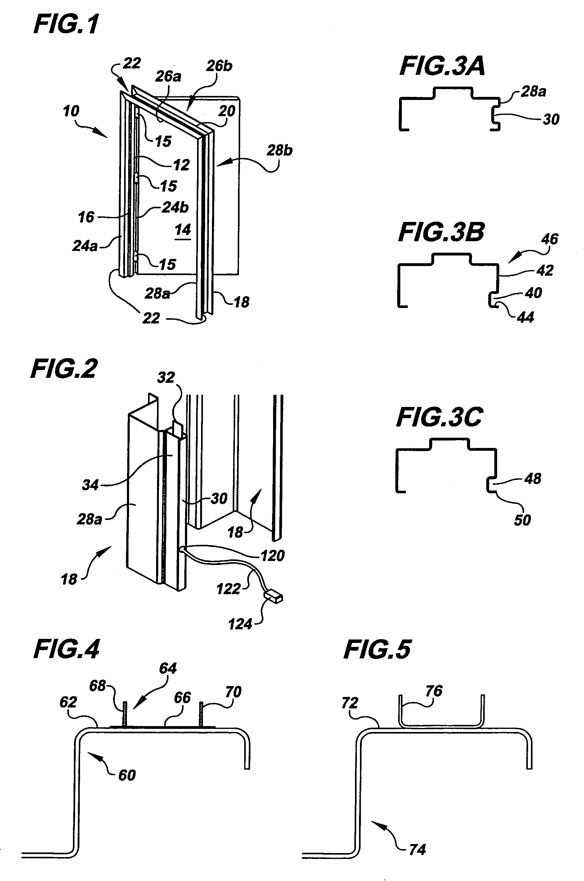
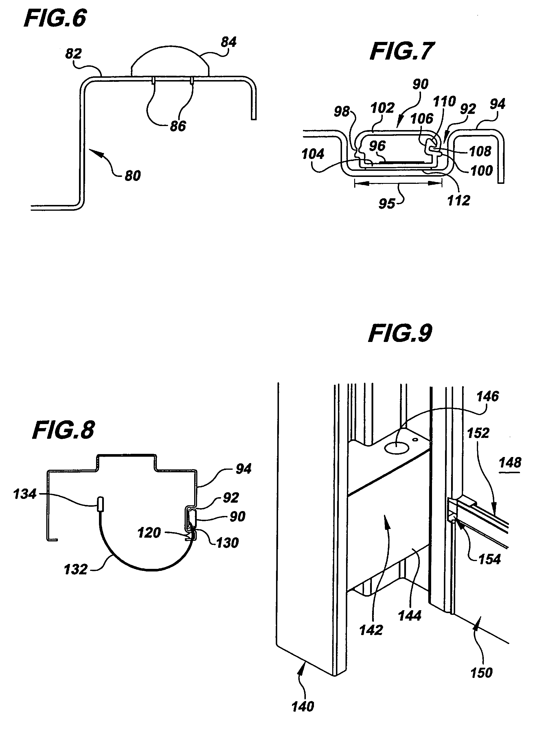
Embodiment Construction

)

[0032]In describing the preferred embodiment of the present invention, reference will be made herein to FIGS. 1–14 of the drawings in which like numerals refer to like features of the invention.

[0033]The invention is directed to illuminating a point of egress using electroluminescent technology. The lighting system is intended to augment EXIT signage that typically is placed above points of egress. The proposed lighting system includes three main components: a) an egress doorframe with integrally formed illuminators that outline available exits, which are generally used in public places during emergencies; b) raceways of electroluminescent strips for illuminating the exit pathway to the points of egress; and c) a bypass doorframe for continuing the electrical connections of the electroluminescent strips around doorways that are not points of egress. Additionally, a flush, low level EXIT sign located in the lower face of an exit door may be used in conjunction with the lighting syst...


PUM


Abstract

A contiguous emergency exit path lighting system that includes the peripheral lighting of a hollow doorframe at an egress point using a set of electroluminescent illuminators integrally formed within or upon the doorframe, an electrical bypass doorframe to reroute wiring around doorways that are not points of egress, electroluminescent illuminator strips mountable on walls, floors, and other pathway surfaces, and flush mount exit signage on the egress door to enhance visibility in high smoke and high heat applications. An integrally formed U-shaped channel within the egress doorframe secures a transparent or translucent raceway tube that encloses the electroluminescent strips.

Description

BACKGROUND OF THE INVENTION[0001]1. Field of the Invention[0002]This invention relates to emergency lighting, typically for the interior of buildings and large vehicles, and specifically for lighting around and directed to points of egress. More specifically, the invention relates to a contiguous emergency exit path lighting system that includes the lighting of a hollow doorframe at an egress point, an electrical bypass doorframe for doorways that are not points of egress, and flush mount exit signage to enhance visibility in high smoke and high heat applications.[0003]2. Description of Related Art[0004]There continually exists a need to provide illuminated egress routes for people who do not know the way, or for those in a panic situation who fail to recognize the closest and most efficient exit pathway. Many systems exist to provide guidance for persons in buildings, vehicles, or other closed spaces to escape routes during emergencies or non-emergency situations. To safely evacuat...

Claims


Application Information

Patent Timeline
Patent Type & Authority Patents(United States)
IPC IPC(8): F21S8/02E04C2/54E06B1/04G09F7/08
CPCE06B1/52E06B7/28G08B7/062G08B7/066G09F19/22F21S4/003F21Y2105/00F21S4/20
Inventor DEDIC, DAVID JRATTAY, THOMAS L
Owner AADG INC
Learn More