
Spectrum analyzer with phase noise compensation

a phase noise compensation and analyzer technology, applied in the field ofspectrum analyzers, can solve the problems of spectrum measurement becoming contrary to fact, unable to tolerate, and the phase noise level of a local oscillator increases, and achieves the effect of suppressing the phase noise of the local oscillator, without creating any spurious responses

Inactive Publication Date: 2006-10-17
GUZIK TECHN ENTERPRISES
View PDF5 Cites 14 Cited by
  • Summary
  • Abstract
  • Description
  • Claims
  • Application Information

AI Technical Summary

Benefits of technology

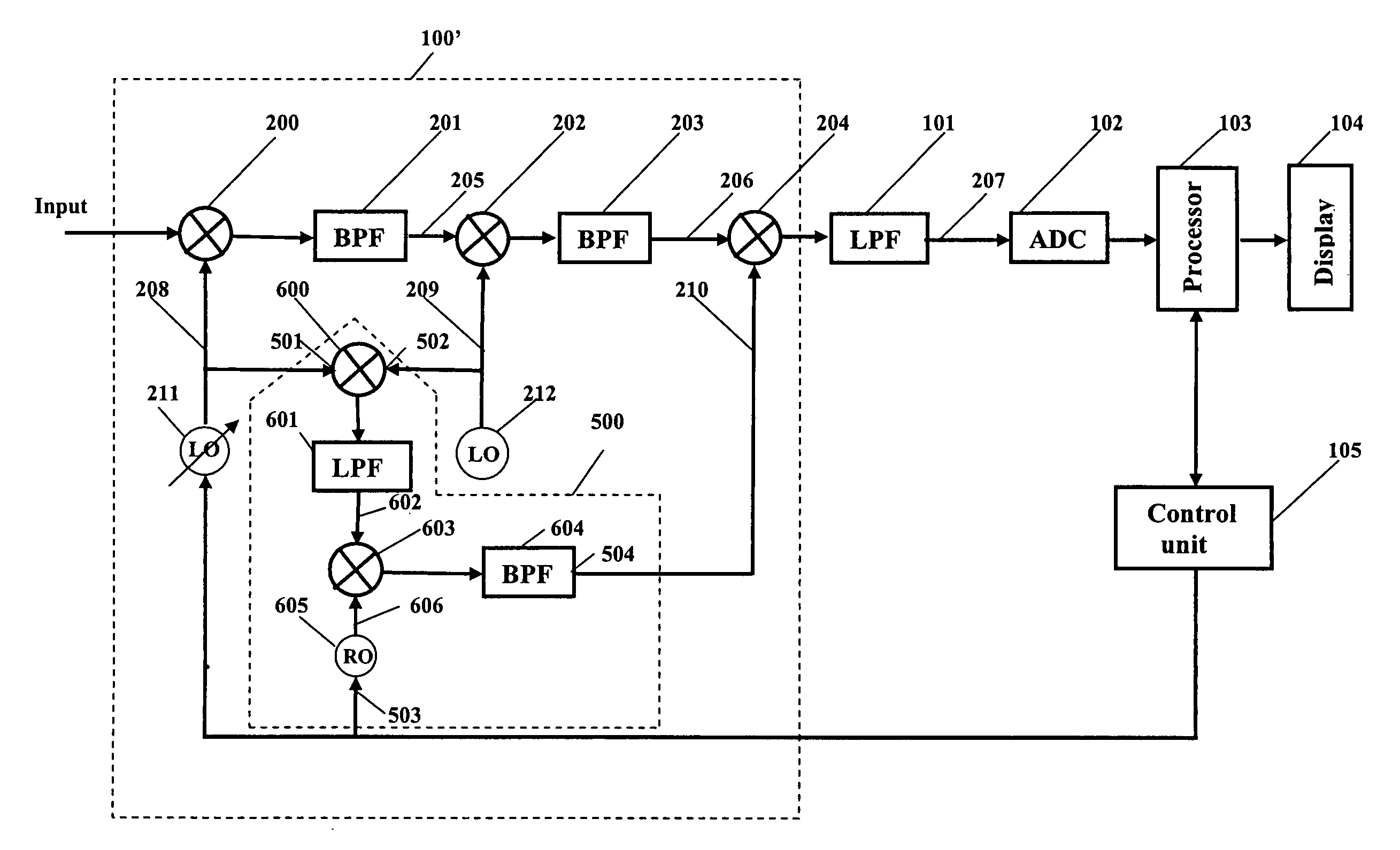
"The present invention provides a spectrum analyzer with suppression of phase noise and without creating spurious responses. This is achieved by incorporating a phase noise compensation unit in a three-stage frequency converter at the input. The phase noise compensation unit produces a signal with the same phase noise as the local oscillators, which cancels out the phase noise of the second and third local signals during the mixing process. The resulting signal has a negligibly small phase noise. The phase noise compensation unit consists of a first auxiliary frequency converter, a second auxiliary frequency converter, and a reference oscillator. The first auxiliary frequency converter processes the local signals and generates a signal with the same phase noise. The second auxiliary frequency converter removes spurious components from the output signal. The third auxiliary frequency converter creates a signal with the desired frequency and the same phase noise. A delay line can also be inserted in the path of the processed signal before the third stage of conversion."

Problems solved by technology

The phase noise level of a local oscillator grows when the oscillator frequency is relatively high.
The results of the spectrum measurements become contrary to fact and that cannot be tolerated.

Method used


Image

  • Spectrum analyzer with phase noise compensation
  • Spectrum analyzer with phase noise compensation
  • Spectrum analyzer with phase noise compensation

Examples


Embodiment Construction

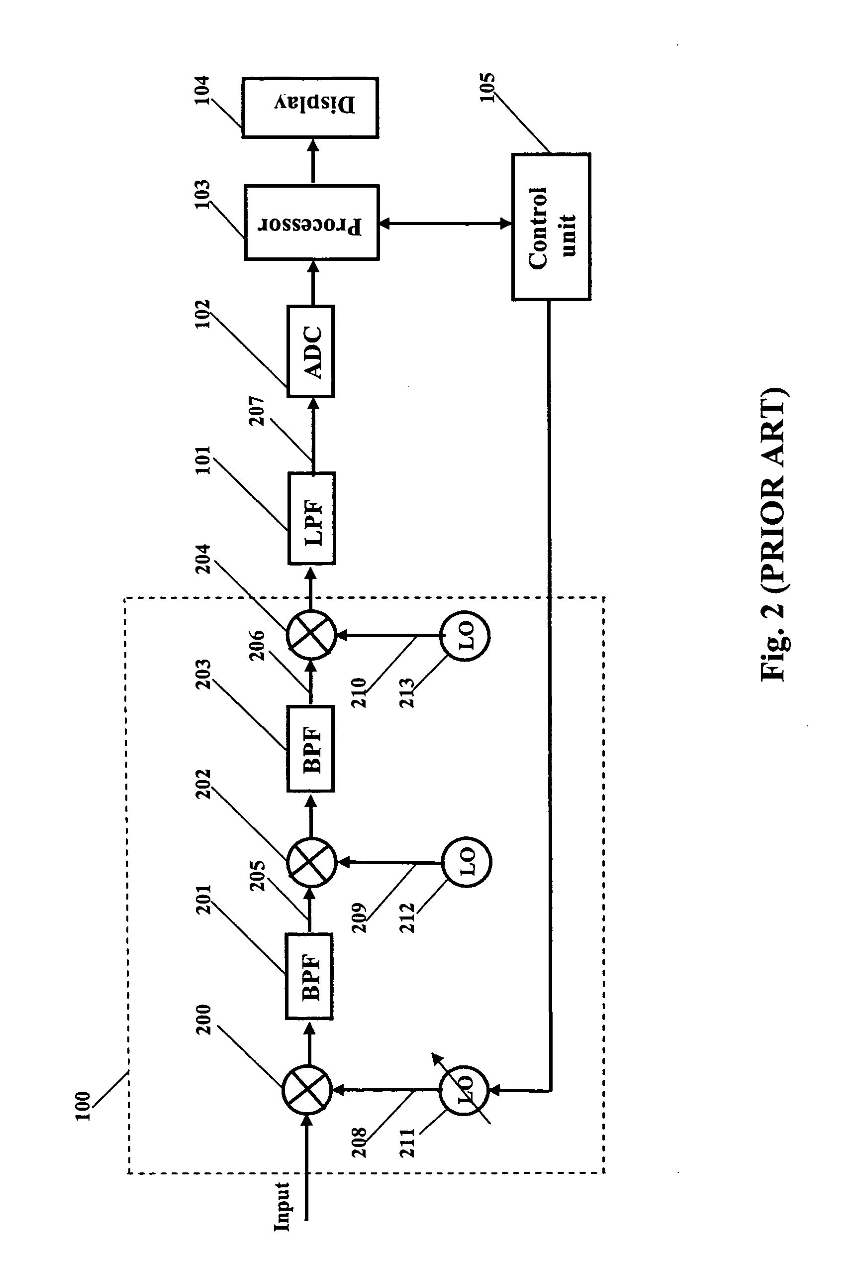
[0034]A block diagram of a basic embodiment of a spectrum analyzer according to the present invention is shown at FIG. 5. In FIG. 5, the frequency converter 100′ differs from that in FIG. 1, but the remaining blocks 101, 102, 103, 104, and 105 can be similar to the correspondingly numbered blocks in FIG. 1. The frequency converter 100′ includes a first mixer 200, a first band pass filter (BPF) 201, a second mixer 202, a second band pass filter (BPF) 203, a third mixer 204, the first local (variable frequency) oscillator 211 and the second (fixed frequency) local oscillator 212, all similar to correspondingly numbered elements in FIG. 2.

[0035]A phase noise compensation unit 500 is incorporated in the frequency converter 101′ of spectrum analyzer. Two signal inputs 501 and 502 of the phase noise compensation unit 500 are connected to the outputs of the first local oscillator 211 and the second local oscillator 212 respectfully. A control input 503 of the phase noise compensation unit ...


PUM


Abstract

A spectrum analyzer with a compensation circuitry for prevention of measurement accuracy deterioration due to local oscillators phase noise.

Description

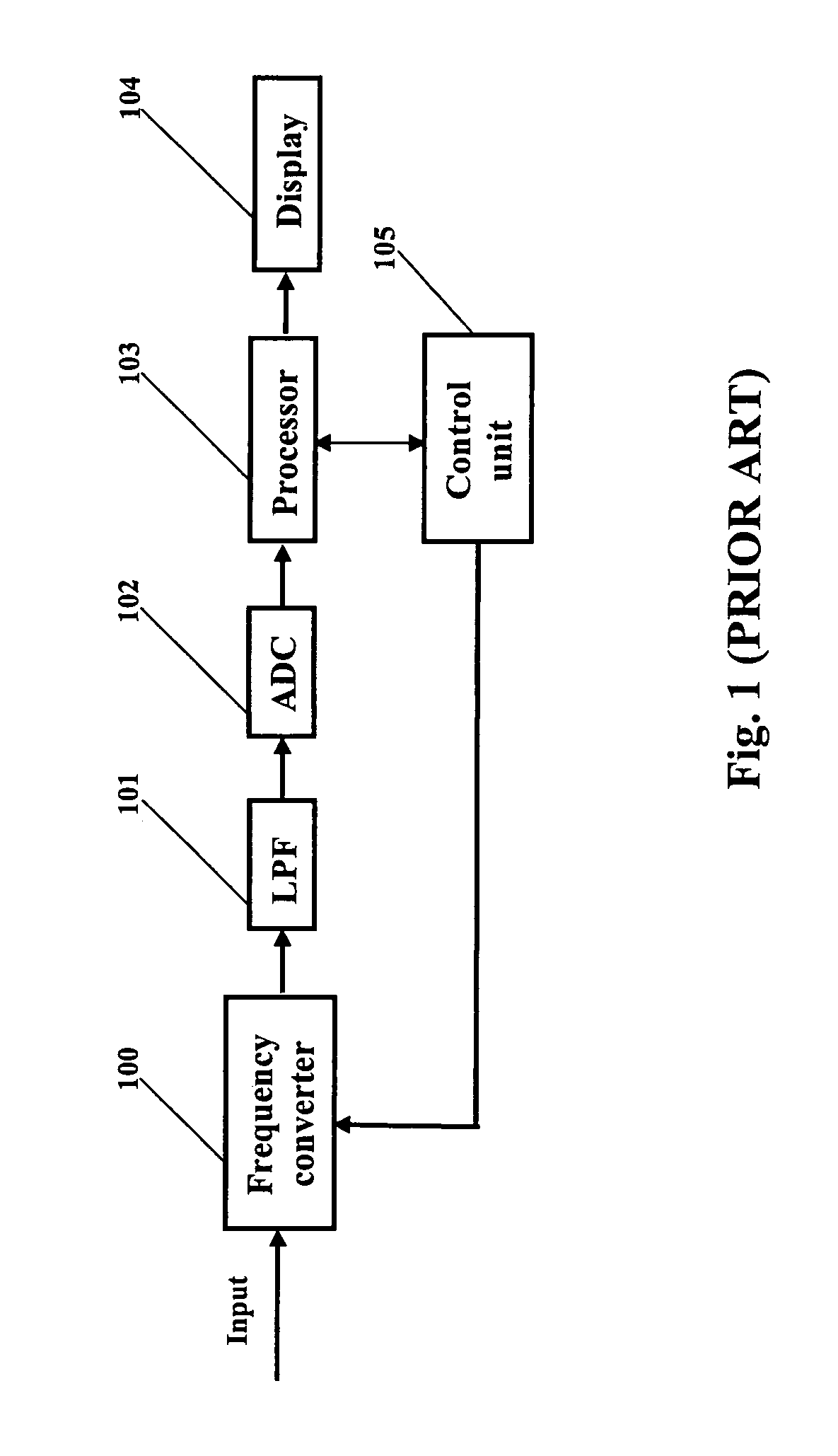
FIELD OF THE INVENTION[0001]The present invention relates to spectrum analyzers that analyze the frequency spectrum of an incoming signal and display the spectrum on a frequency domain display. In particular, this invention relates to means for preventing measurement accuracy deterioration in spectrum analyzers that use local oscillators with substantial level of phase noise.BACKGROUND OF THE INVENTION[0002]A spectrum analyzer is a device that measures the power density of an input signal and displays that power density in a form convenient to the user. A typical block diagram of a prior art spectrum analyzer is shown in FIG. 1. The spectrum analyzer of FIG. 1 includes a frequency converter 100, a low pass filter (LPF) 101, an analog-to-digital converter (ADC) 102, a processor 103, a display 104 and a control unit 105. The frequency spectrum of an applied input signal is measured in a step-by-step process. The control unit 105 controls the frequency converter 100 and, in particular,...

Claims


Application Information

Patent Timeline
Patent Type & Authority Patents(United States)
IPC IPC(8): G01R23/16
CPCG01R23/16G01R23/20
Inventor STEIN, ANATOLI B.PANTCHENKO, SERGUEI
Owner GUZIK TECHN ENTERPRISES
Learn More