
Integrated business process modeling environment and models created thereby

a business process and modeling environment technology, applied in the field of graphical object oriented business process modeling environment, can solve the problems of inflexible increased quantity and complexity of point to point connections, and inability to facilitate reconfiguration, so as to increase the flexibility of business process models and modeling environments

Active Publication Date: 2006-10-10
VITRIA TECH
View PDF24 Cites 185 Cited by
  • Summary
  • Abstract
  • Description
  • Claims
  • Application Information

AI Technical Summary

Benefits of technology

[0009]It is an object of the invention to increase the flexibility of business process models and modeling environments. To achieve this and other objects, a first aspect of the invention is a model comprised of a plurality of components coupled together in an object oriented, graphical representation of a computer architecture for executing one or more business processes. At least one of the components comprises executable process logic of a business process, a first port defining a standard interface for data flow between components, and code for looking up connection information stored in a repository. The connection information includes information indicating a second port to which the first port is to be connected, information relating to the type of the second port, and information indicating how to connect to the second port.

Problems solved by technology

Historically, such systems were each handled by dedicated software packages that did not integrate well with each other.
However, as the number of systems increases, the quantity and complexity of point to point connections also increase.
Further, point to point connections are rather inflexible and do not facilitate reconfigurations of systems to accommodate changing business models.
However, due to the complexities of communication between applications, and components, all of these phases are accomplished at different levels of abstraction by separate software tools.
However, the flow charts and other diagrams created by CASE tools are not intended to be directly executed.
Accordingly, it is difficult to develop, deploy, and debug business process management systems because of a lack of unified tools.

Method used


Image

  • Integrated business process modeling environment and models created thereby
  • Integrated business process modeling environment and models created thereby
  • Integrated business process modeling environment and models created thereby

Examples


Embodiment Construction

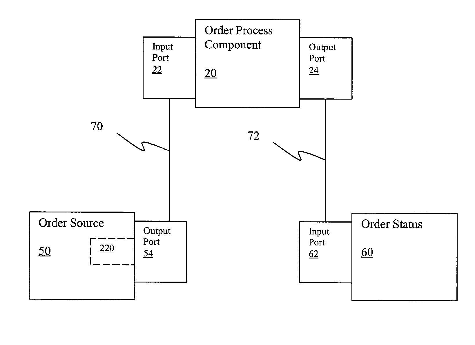
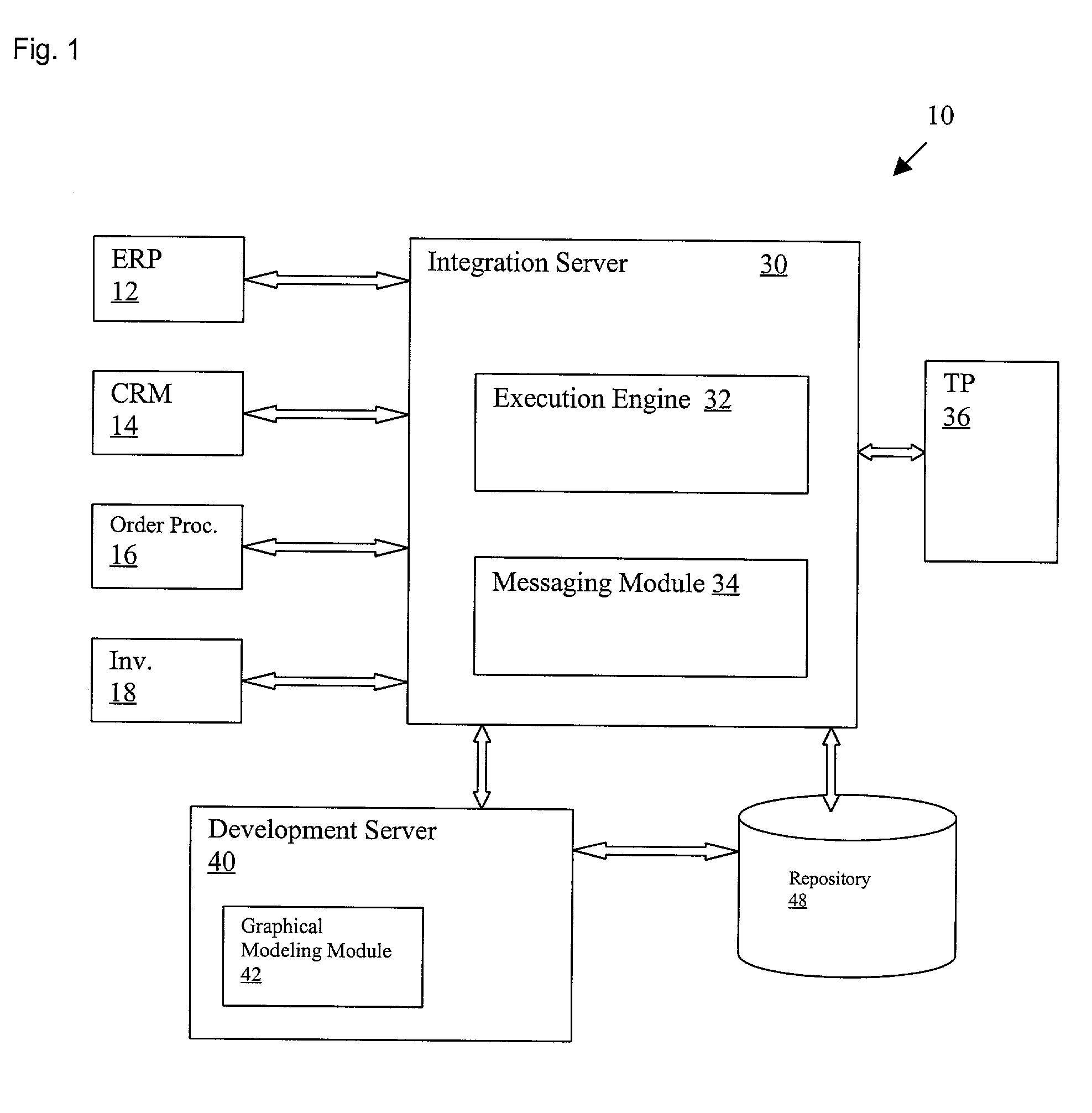
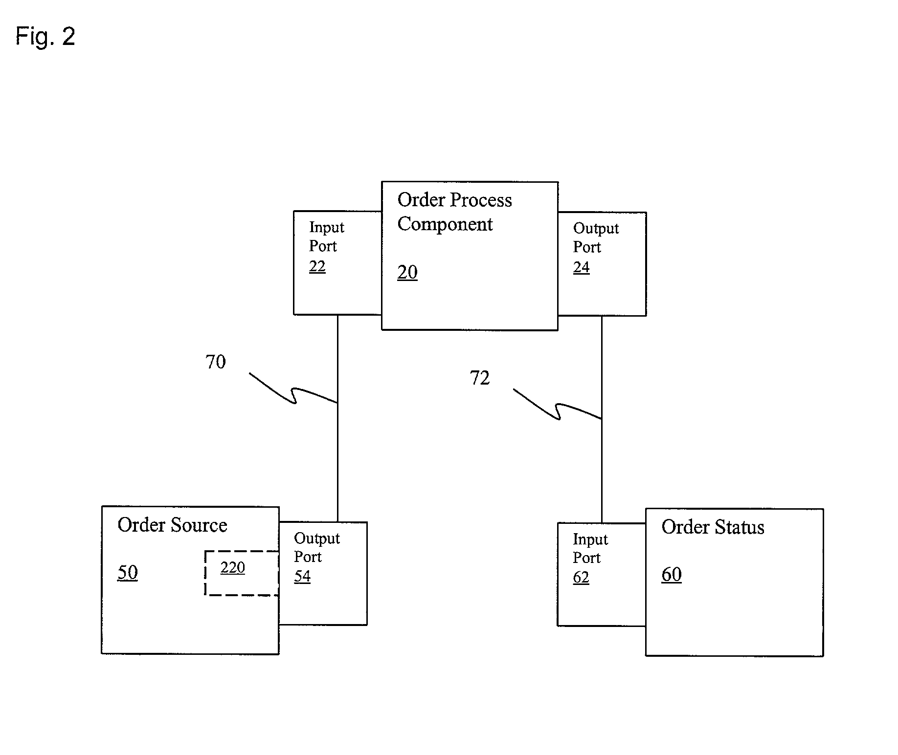
[0037]Applicant has introduced a new type of model, called the “integration model,” that is used to provide a graphical end to end, or global, view of an integration application. The integration model shows how the various business process models in the corresponding integration application are connected to one another and communicate with one another. The integration model allows the application designer to work at multiple levels of abstraction. For example. The application designer can work at the integration model level to model connectivity and the data flow between various business process models and, when desired, can “drill down” into the business process model to create or modify the details of the individual business processes. The integration model can be debugged, deployed for execution, and directly executed by a runtime environment.

[0038]Applicant has developed a graphical modeling environment in which business process logic of components is separated from the communic...


PUM


Abstract

An integrated modeling environment for creating integration models of computer architecture for executing business processes. The models include components having ports defining standard interfaces. The components can represent business process models for executing business processes. Connection information is stored in a repository so that binding of communication protocols can occur during deployment after creation of the model and can be looked up during runtime.

Description

BACKGROUND[0001]The present invention relates generally to a graphical object oriented business process modeling environment and more specifically to such an environment in which interacting components representing business processes can be created, manipulated, tested, deployed, and executed in a flexible manner.[0002]It is well known to automate various business systems, such as Customer Relations Management (CRM), Enterprise Resource Planning (ERP), accounting, inventory control, order processing and the like. Historically, such systems were each handled by dedicated software packages that did not integrate well with each other. Early software programs for automating business systems were designed to run independently, with no interaction between various systems. Such programs were custom built for a specific need being addressed and often utilized proprietary protocols. Dedicated “point to point” connections were developed to permit each such system to communicate with another s...

Claims


Application Information

Patent Timeline
IPC IPC(8): G06F9/44G06F17/00G06F9/46G06F7/10G06F7/60G06F9/45G06F9/455G06F15/177
CPCG06F8/20
Inventor BUDHIRAJA, NAVINSKEEN, MARION DALEWANG, HAIYINGRUBIN, ELISA JILLBANERJEE, DEB
Owner VITRIA TECH
Learn More