
Method for calibrating steam generator water level measurement

a technology of steam generators and water level measurement, applied in water feed control, greenhouse gas reduction, instruments, etc., can solve problems such as errors, and achieve the effect of reducing operating margins

Active Publication Date: 2006-10-10
WESTINGHOUSE ELECTRIC CORP
View PDF12 Cites 14 Cited by
  • Summary
  • Abstract
  • Description
  • Claims
  • Application Information

AI Technical Summary

Problems solved by technology

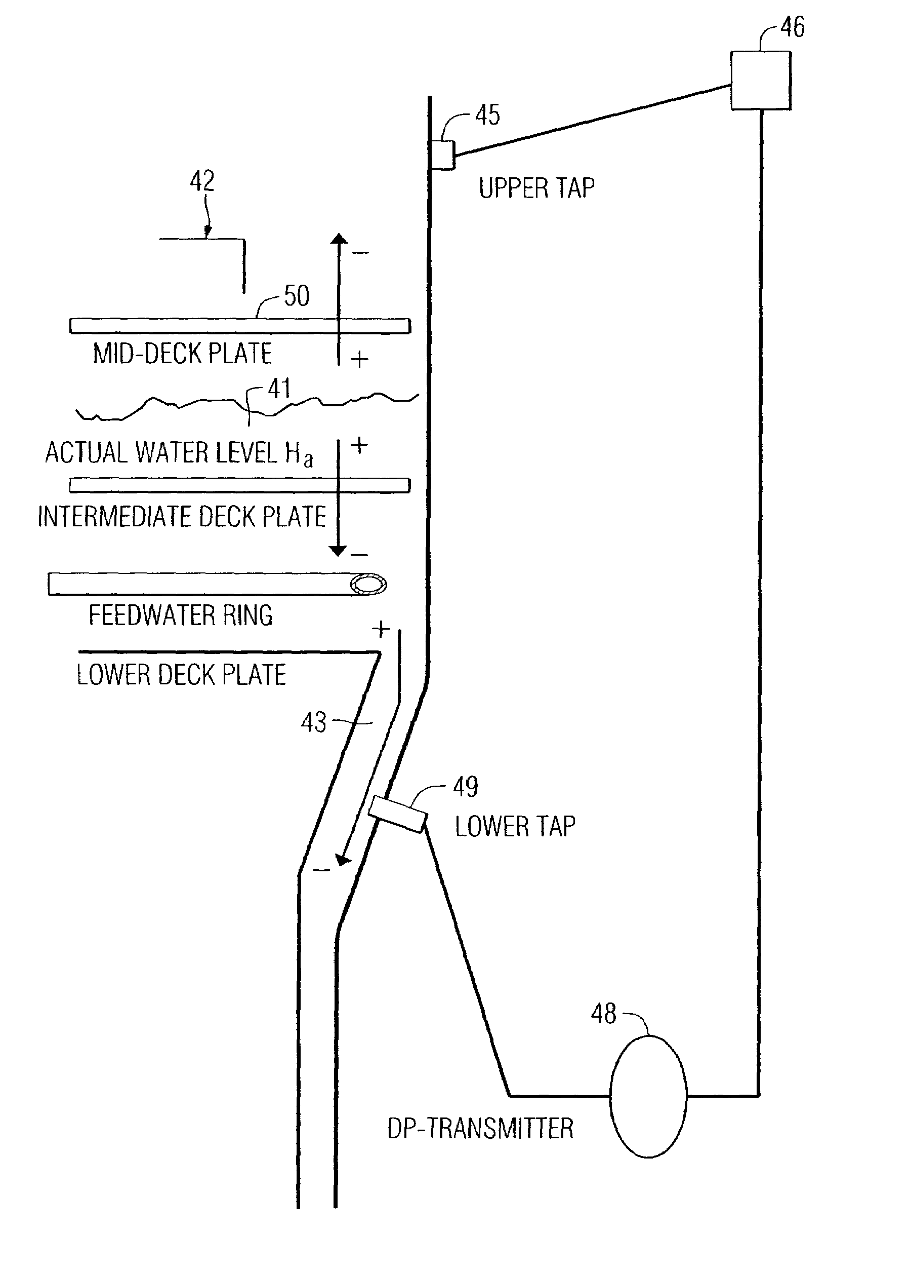
However, if the lower pressure tap is moved to a higher velocity region, e.g., below the transition portion of the shell, an error is introduced due to the effective velocity head of the moving water.

Method used


Image

  • Method for calibrating steam generator water level measurement
  • Method for calibrating steam generator water level measurement
  • Method for calibrating steam generator water level measurement

Examples


Embodiment Construction

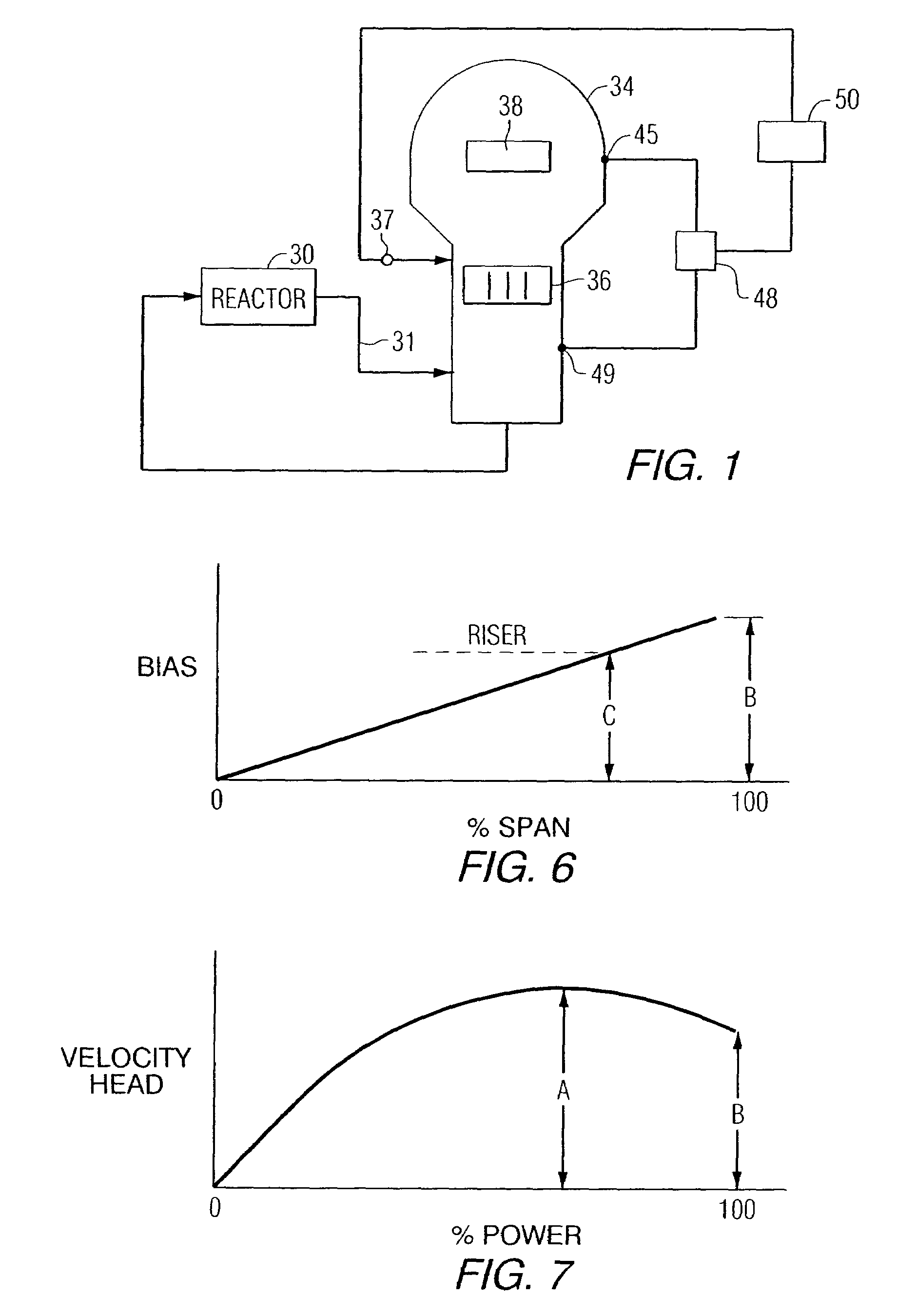
[0019]FIG. 1 shows a rudimentary block diagram of a typical pressurized water reactor system. The reactor 30 generates hot water which is coupled through suitable piping 31, commonly referred to as the hot leg of the primary coolant loop, to a steam generator 34. The water coolant from the reactor is circulated through heat transfer tubes illustrated at 36, where it imparts its heat to feed water introduced as shown at 37, and then is returned to the reactor. The rising steam generated from heating the feed water is passed through moisture separation apparatus illustrated at 38. As is well known, there is a minimum level of feed water that must be maintained in the steam generator, to draw heat from the primary loop of the reactor so that the reactor does not overheat. There is also a maximum level of feed water that should be maintained within the steam generator which, if exceeded, would prevent the moisture separators from properly separating moisture from the steam.

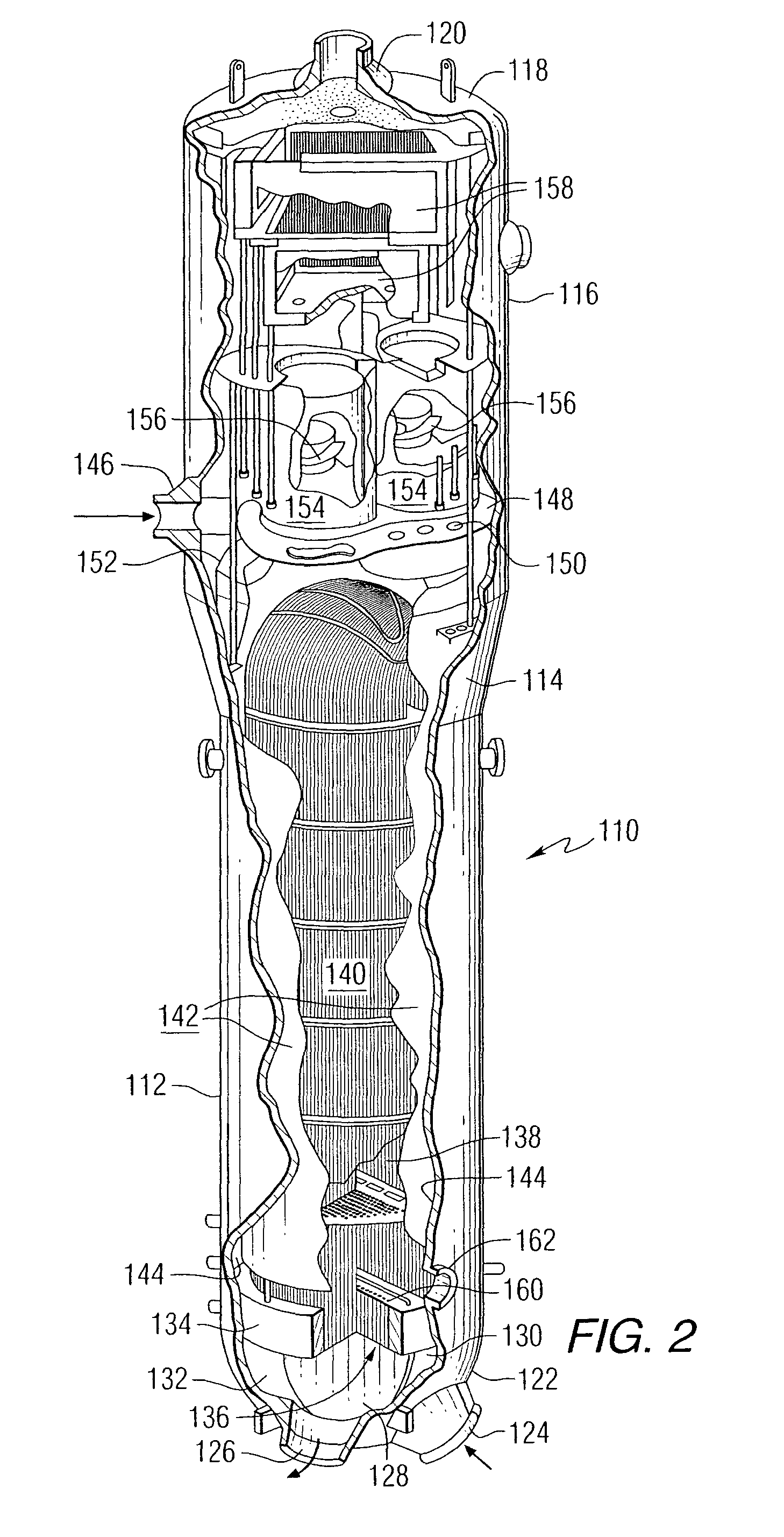
[0020]FIG. 2 ...


PUM


Abstract

A method is provided for determining and controlling feed water level in a steam generator of a nuclear power plant, whereby the water level sensor is calibrated in terms of the pressure drop across structural components in the feed water path. The water level differential pressure sensor is calibrated so that maximum water level is indicated as the level corresponding to the upper tap level plus the pressure drop across the foregoing structural components at maximum power plant power.

Description

CROSS-REFERENCE TO RELATED APPLICATION[0001]This application claims priority under 35 U.S.C. §119(e) to provisional application Ser. No. 60 / 413,511, filed Sep. 25, 2002.BACKGROUND OF THE INVENTION[0002]1. Field of the Invention[0003]This invention relates to a method for determining the feed water measurement in a steam generator such as those used in pressurized water reactors and, more particularly, to a method for using a differential-type transmitter to sense the feed water level in a steam generator in a nuclear power plant.[0004]2. Related Art[0005]A typical nuclear steam generator comprises a vertically-oriented shell; a plurality of U-shaped tubes disposed in the shell so as to form a tube bundle; a tube sheet for supporting the tubes at the ends opposite the U-like curvature; a dividing plate that cooperates with the tube sheet forming a primary fluid inlet header at one end of the tube bundle and a primary fluid outlet header at the other end of the tube bundle; a primary ...

Claims


Application Information

Patent Timeline
Patent Type & Authority Patents(United States)
IPC IPC(8): G21C7/32
CPCG21D3/12G21Y2002/201G21Y2002/204G21Y2004/403Y02E30/40Y02E30/00Y02E30/30
Inventor SRINIVASAN, JAGANNATHAN SEENU
Owner WESTINGHOUSE ELECTRIC CORP
Learn More