
Method for determining the relative speed of an object

a technology of relative speed and measurement method, applied in the direction of distance measurement, instruments, and reradiation, can solve the problems of unsatisfactory time delay in the provision of measurement, radiation power, eye injury of persons or animals, etc., and achieve the effect of increasing the intended protective effect for the vehicle occupants

Active Publication Date: 2006-10-10
CONTI TEMIC MICROELECTRONIC GMBH
View PDF9 Cites 4 Cited by
  • Summary
  • Abstract
  • Description
  • Claims
  • Application Information

AI Technical Summary

Benefits of technology

[0014]The inventive method is best suited for the use in an occupant restraint system for motor vehicles. In such an application, the inventive method serves for the pre-crash sensing, that is to say the recognition of the danger of an imminent collision of the motor vehicle with an object approaching the motor vehicle. If such a danger is recognized, then triggering criteria for restraint means, for example for an airbag, can be suitably adapted to a possible accident scenario. This leads to a more-targeted triggering of the restraint means and thus an increase of the intended protective effect for the vehicle occupants.

Problems solved by technology

While this could be determined through a differentiation of the time course or progression of the object separation, the result, however, would be inexact due to the noise increased or amplified through the differentiation.
While the signal-to-noise ratio of the measurement result could be suppressed through a filtering, the filtering would, however, lead to an undesired time delay in the providing of the measurement result.
Furthermore, it would be conceivable to improve the signal-to-noise ratio through increasing of the radiation power of the laser source, but an increasing of the radiation power is not desired, because this could lead to an eye injury of persons or animals that might look in the direction of the laser source.

Method used


Image

  • Method for determining the relative speed of an object
  • Method for determining the relative speed of an object
  • Method for determining the relative speed of an object

Examples


Embodiment Construction

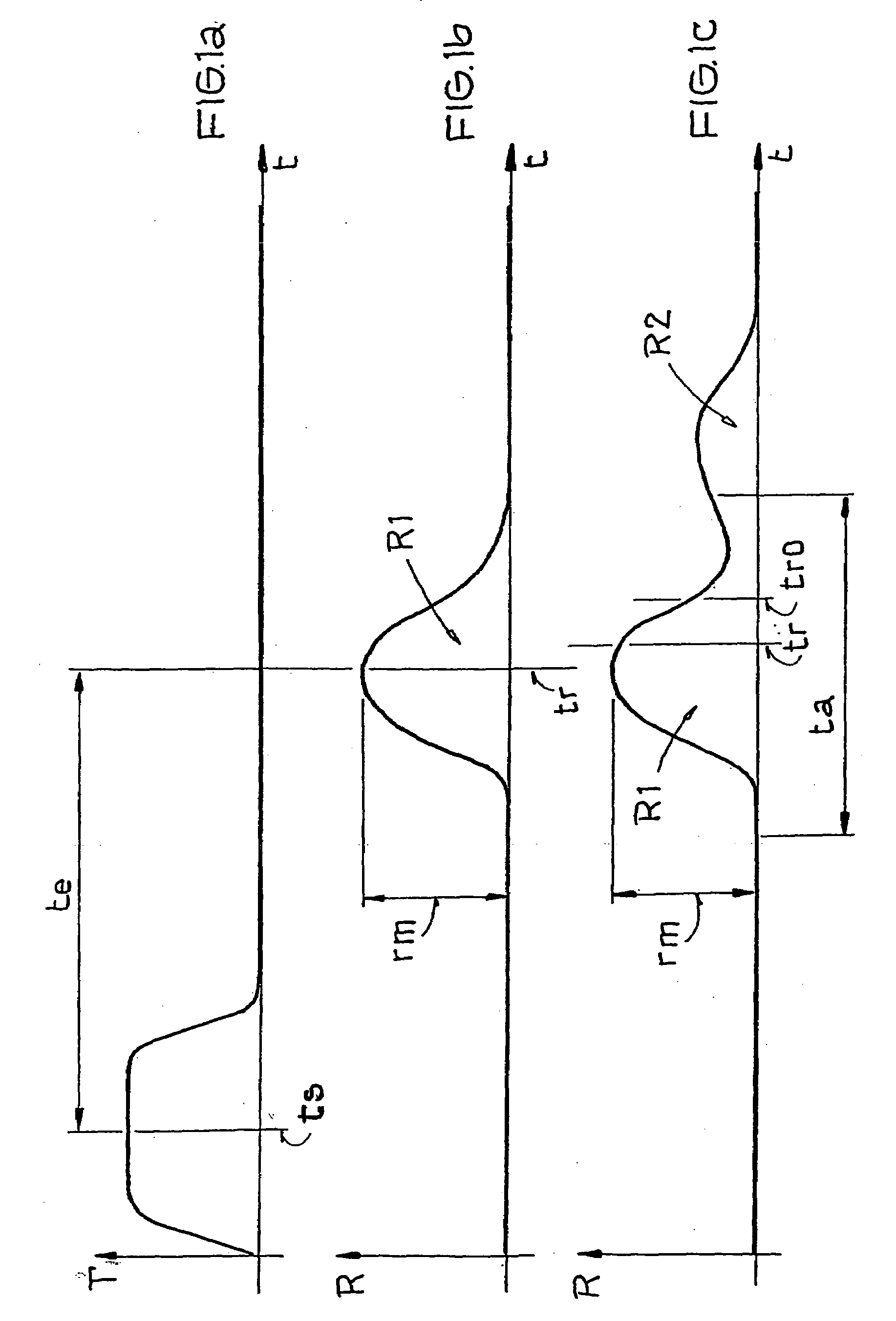
[0020]The inventive method is utilized in an occupant restraint system for motor vehicles for the pre-crash sensing. In that context, the likelihood or probability of an imminent collision is estimated through detection of objects that are located within a measurement space in front of the motor vehicle, and through determination of the speed of objects that, if applicable, approach the motor vehicle. The objects are detected through emitting of light pulses and detection of the light pulses reflected back from the objects, whereby the light pulses are advantageously emitted sequentially into various different spatial sections or segments of the measurement space respectively representing a channel and are detected in a channel-referenced manner, in order to obtain, in addition to the separation or spacing distance information, also an information about the location range of the object reflecting the respective light pulse. Then, the object separations or spacing distances are deter...


PUM


Abstract

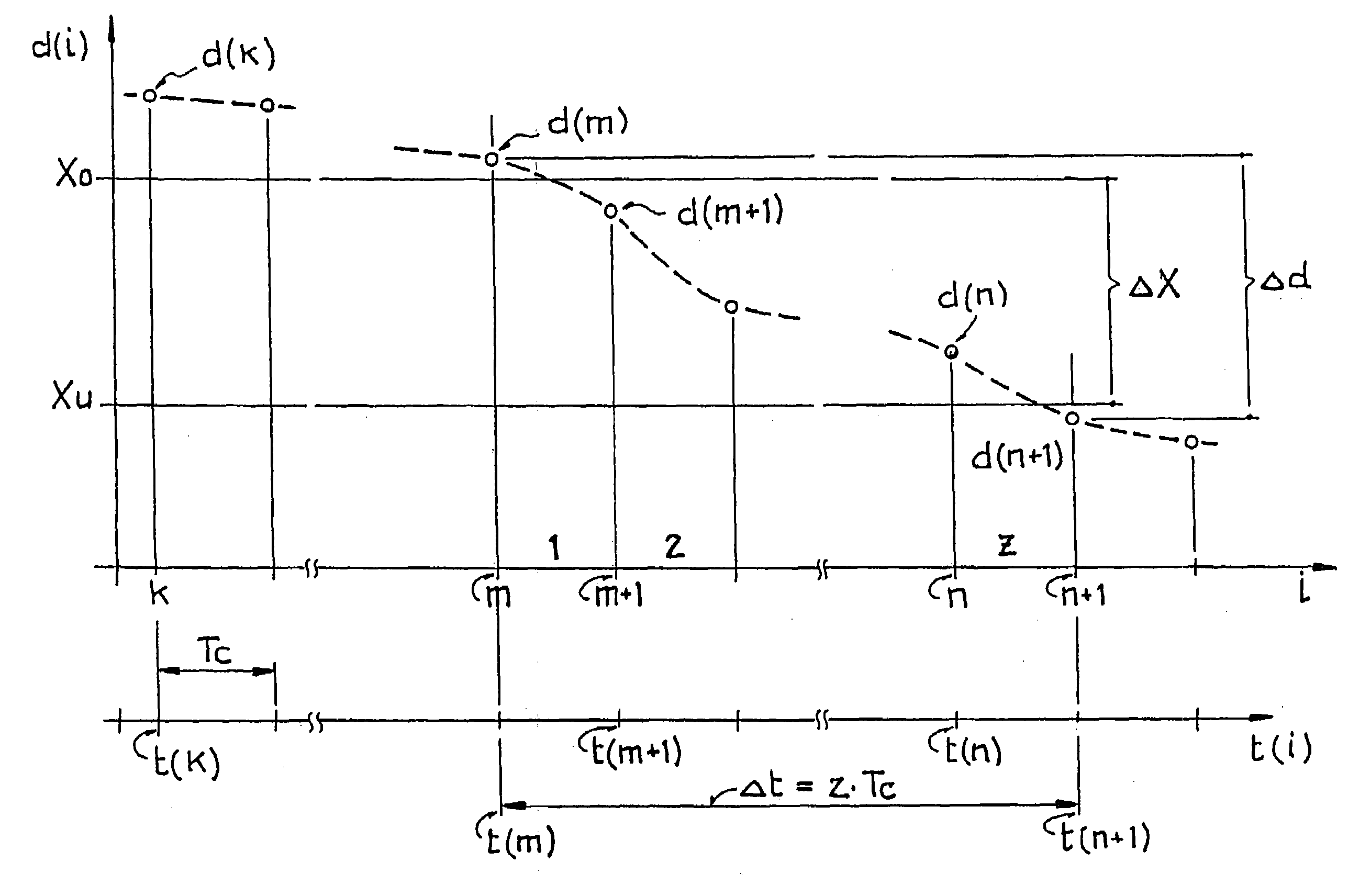
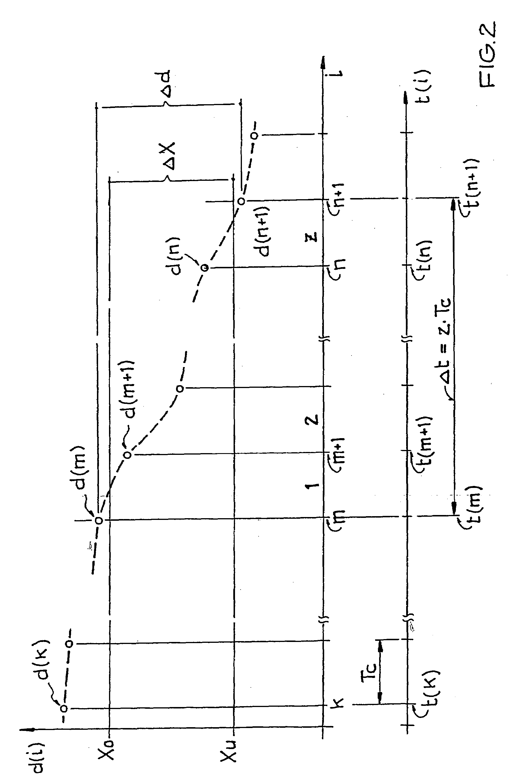
Methods for the measurement of the object spacing distance or separation of objects are increasingly utilized in obstacle warning systems for motor vehicles, in order to warn the drivers of the motor vehicles of sources of danger on the roadway. It would be sensible or suitable in such a system, to take into account also the relative speed of objects approaching the motor vehicle. The new method shall enable the determination of the relative speed of an object in a simple manner and provide exact measurement results. In the new measurement method, the object separation is cyclically determined respectively after expiration of a prescribed cycle period. Furthermore, the number of the cycles is determined, within which the object separation changes so far that a prescribed separation band is completely traversed. The relative speed of the object is then calculated from the difference between the object separation determined before the entry into the separation band and the object separation determined after the exit out of the separation band, and from the determined number of cycles. Pre-crash sensing.

Description

BACKGROUND OF THE INVENTION[0001]The invention relates to a method for the measurement of the relative speed of an object according to patent claim 1.[0002]Methods for the determination of object separations or spacing distances are increasingly utilized in obstacle warning systems for motor vehicles, in order to warn the drivers of the motor vehicles of sources of danger on the roadway. For example, a method for the obstacle recognition is known from the DE 41 15 747 C2, in which an observation or monitoring space in front of a vehicle is repeatedly sensed or sampled with a laser source, in order to calculate the object separation or spacing distance from the signal transit time of the light emitted from the laser source and reflected on an object, and to warn the driver, through acoustic or optical signals, of a possible collision with the object, depending on the determined object separation.[0003]It would be sensible or suitable in the estimation of the collision probability, to...

Claims


Application Information

Patent Timeline
IPC IPC(8): G01P3/26G01C3/08G01S17/931G01S13/58G01S13/64G01S13/931G01S17/58
CPCG01S17/58G01S17/936G01S13/588G01S13/64G01S13/931G01S2013/9367G01S2013/9323G01S17/931
Inventor BEUSCHEL, MICHAELNASTASIE, ALEXANDER
Owner CONTI TEMIC MICROELECTRONIC GMBH
Learn More