
Oscillation circuit and operation method thereof

a technology of oscillating circuit and operation method, which is applied in the direction of pulse generator, pulse generation by vacuum tube, pulse technique, etc., can solve the problems of many semiconductor devices with malfunctions, and achieve the effects of suppressing the influence of threshold voltage variation, and reducing oscillation frequency variation

Inactive Publication Date: 2006-10-10
NEC ELECTRONICS CORP
View PDF3 Cites 0 Cited by
  • Summary
  • Abstract
  • Description
  • Claims
  • Application Information

AI Technical Summary

Benefits of technology

[0009]An object of the present invention is generally to provide a technique for reducing variation in oscillation frequency of an oscillation circuit.
[0010]More specifically, an object of the present invention is to provide an oscillation circuit including an astable multivibrator with two capacitors and a charge-discharge circuit for alternately charging and discharging the capacitors, which suppresses the influence of the variation in threshold voltages of MOS transistors constituting a feedback path for providing a feedback of voltages generated in the capacitors to the charge-discharge circuit, and thereby reduces the variation in the oscillation frequency.
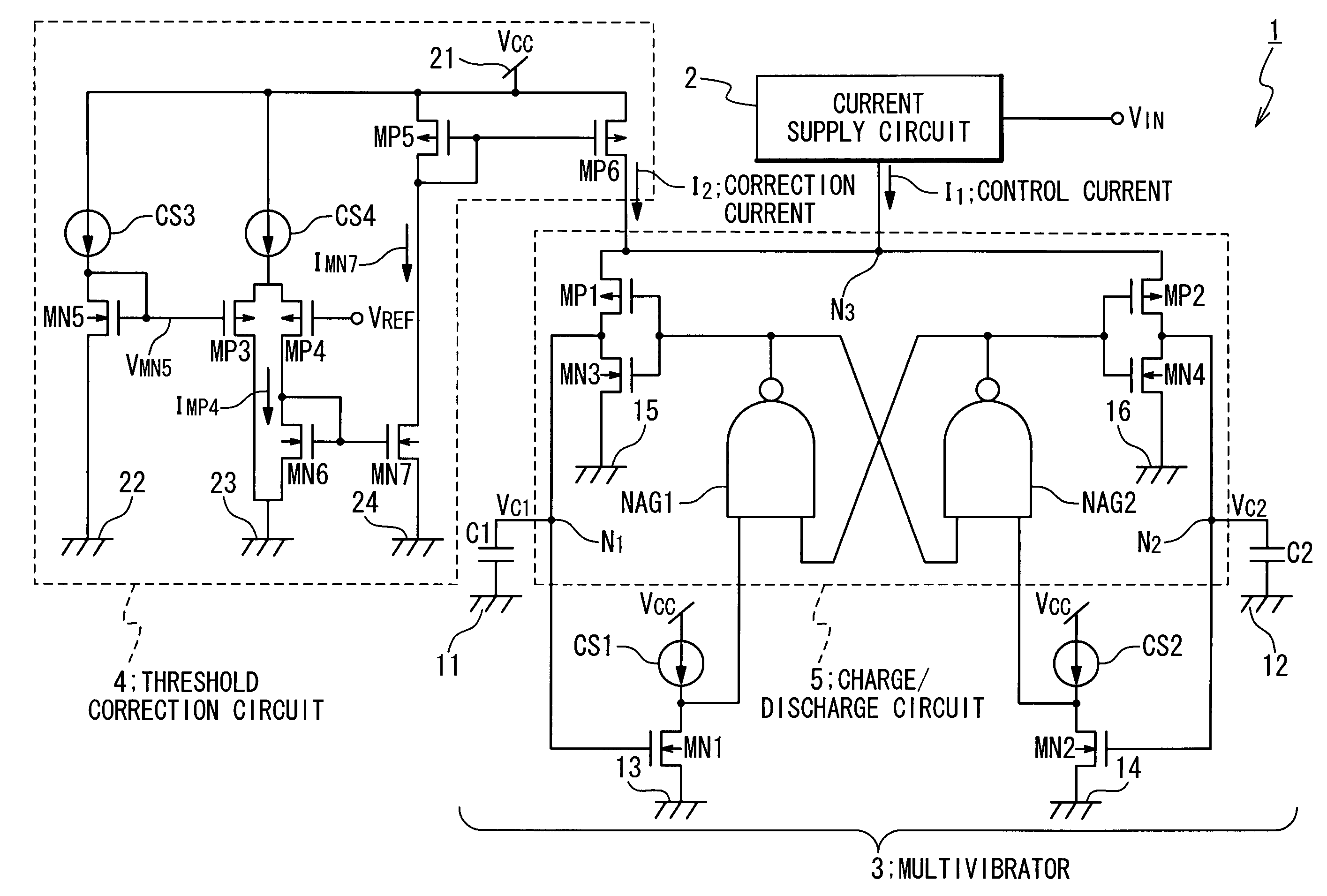
[0013]The threshold voltage of the third MOS transistor formed on the same semiconductor substrate as the first and the second MOS transistors varies in a similar way to the threshold voltages of the first and the second MOS transistors. Therefore, the threshold correction circuit can generate the correction current in response to the threshold voltages of the first and the second MOS transistors. The first and the second MOS transistors feed back the potentials of the first node and the second node to the charge-discharge circuit, respectively. Thus, the oscillation circuit according to the present invention can suppress the variation in the oscillation frequency caused by the variation in the threshold voltage of the first or the second MOS transistor.
[0015]The threshold correction circuit can further has a constant current source. In this case, the third MOS transistor has a drain connected to the constant current source, a gate connected to the drain, and a source connected to a third terminal with the predetermined potential. The correction current supplying circuit preferably generates the correction current in response to a potential of the gate of the third MOS transistor. When the threshold correction circuit has such the configuration, the potential of the gate of the third MOS transistor is associated with the threshold voltage of the third MOS transistor. Therefore, by using the potential of the gate of the third MOS transistor, it is possible to generate the correction current appropriately.
[0019]According to the present invention, a technique is provided for reducing the variation in the oscillation frequency of the oscillation circuit.
[0020]More specifically, provided according to the present invention is an oscillation circuit including an astable multivibrator with two capacitors and a charge-discharge circuit for alternately charging and discharging the capacitors, which suppresses the influence of the variation in threshold voltages of MOS transistors constituting a feedback path for providing a feedback of voltages generated in the capacitors to the charge-discharge circuit, and thereby reduces the variation in the oscillation frequency.

Problems solved by technology

When a considerable number of semiconductor devices having the oscillation circuit are manufactured, large variation in the oscillation frequencies causes malfunctions in many semiconductor devices.

Method used


Image

  • Oscillation circuit and operation method thereof
  • Oscillation circuit and operation method thereof

Examples


Embodiment Construction

[0022]Embodiments of the present invention will be described below with reference to the attached drawings.

1. Configuration of Oscillation Circuit

1.1. General Configuration

[0023]FIG. 1 is a block diagram showing a configuration of an oscillation circuit in an embodiment of the present invention. The oscillation circuit 1 is a voltage controlled oscillator (VCO). The oscillation circuit 1 has a current supply circuit 2, a multivibrator 3, and a threshold correction circuit 4. The current supply circuit 2, the multivibrator 3 and the threshold correction circuit 4 are monolithically integrated onto a semiconductor chip. In response to a control voltage VIN, the current supply circuit 2 supplies a control current I1 to a node N3 of the multivibrator 3. The threshold correction circuit 4 supplies a correction current I2 to the node N3. The correction current I2 is superposed on the control current I1 at the node N3, which generates a charge current. The multivibrator 3 uses the charge c...


PUM


Abstract

An oscillation circuit has: a first MOS transistor having a gate connected to a first node and a source connected to the ground; a second MOS transistor having a gate connected to a second node and a source connected to the ground; a current supply circuit supplying a control current; a threshold correction circuit supplying a correction current; and a charge-discharge circuit which supplies a charge current which is a superposition of the control current and the correction current to the first node and the second node alternately in response to potentials of drains of the first and the second MOS transistors. The threshold correction circuit increases the correction current as threshold voltages of the first and the second MOS transistors become large.

Description

BACKGROUND OF THE INVENTION[0001]1. Field of the Invention[0002]The present invention relates to an oscillation circuit. In particular, the present invention relates to an oscillation circuit including an astable multivibrator.[0003]2. Description of the Related Art[0004]An oscillation circuit is often configured with an astable multivibrator. A typical astable multivibrator charges and discharges two capacitors alternately to generate oscillation waveforms. A circuit for charging and discharging these capacitors is mounted in such the astable multivibrator. The voltages applied to the capacitors are fed back to the charge-discharge circuit, and the charge-discharge circuit charges and discharges the two capacitors in response to the applied voltages.[0005]Oscillation frequency of the astable multivibrator is determined by the time required for charging and discharging the two capacitors. This charge-discharge time can be controlled easily by adjusting a charging current for chargin...

Claims


Application Information

Patent Timeline
Patent Type & Authority Patents(United States)
IPC IPC(8): H03L7/00H03K3/354H03B1/00H03K3/011H03K3/03
CPCH03K3/011H03K3/03
Inventor YOSHIDA, JUN
Owner NEC ELECTRONICS CORP
Learn More