
Flow sensor

a flow sensor and flow rate technology, applied in the field of flow sensors, can solve the problem that the flow rate sensor cannot be used for corroding gas or liquid, and achieve the effect of less deterioration, less deposited, and stable performan

Inactive Publication Date: 2006-10-10
YAMATAKE HONEYWELL CO LTD
View PDF16 Cites 6 Cited by
  • Summary
  • Abstract
  • Description
  • Claims
  • Application Information

AI Technical Summary

Benefits of technology

[0009]A flow sensor according to the present invention comprises a thin plate-like substrate which forms part of a channel for a fluid, and temperature detecting means formed on that surface of the substrate which is opposite to the channel and including a heat-generating body. According to this arrangement, the temperature detecting means including the heat-generating body is formed on that surface of the substrate which is opposite to the channel. Hence, the fluid does not come into direct contact with the temperature detecting means, so the sensor can be used for measuring a corrosive gas or liquid depending on the material of the substrate. As the temperature detecting means is not exposed to the fluid, dust will be less deposited on it and it will less deteriorate over time due to the fluid, but maintains a stable performance. As the substrate is a thin plate, heat conduction between the fluid and the temperature detecting means is good.

Problems solved by technology

Hence, this flow rate sensor cannot be used for a corrosive gas or liquid which is used in a semiconductor manufacturing apparatus and the like.

Method used


Image

  • Flow sensor
  • Flow sensor
  • Flow sensor

Examples


Embodiment Construction

[0025]The present invention will be described in detail with reference to the drawings.

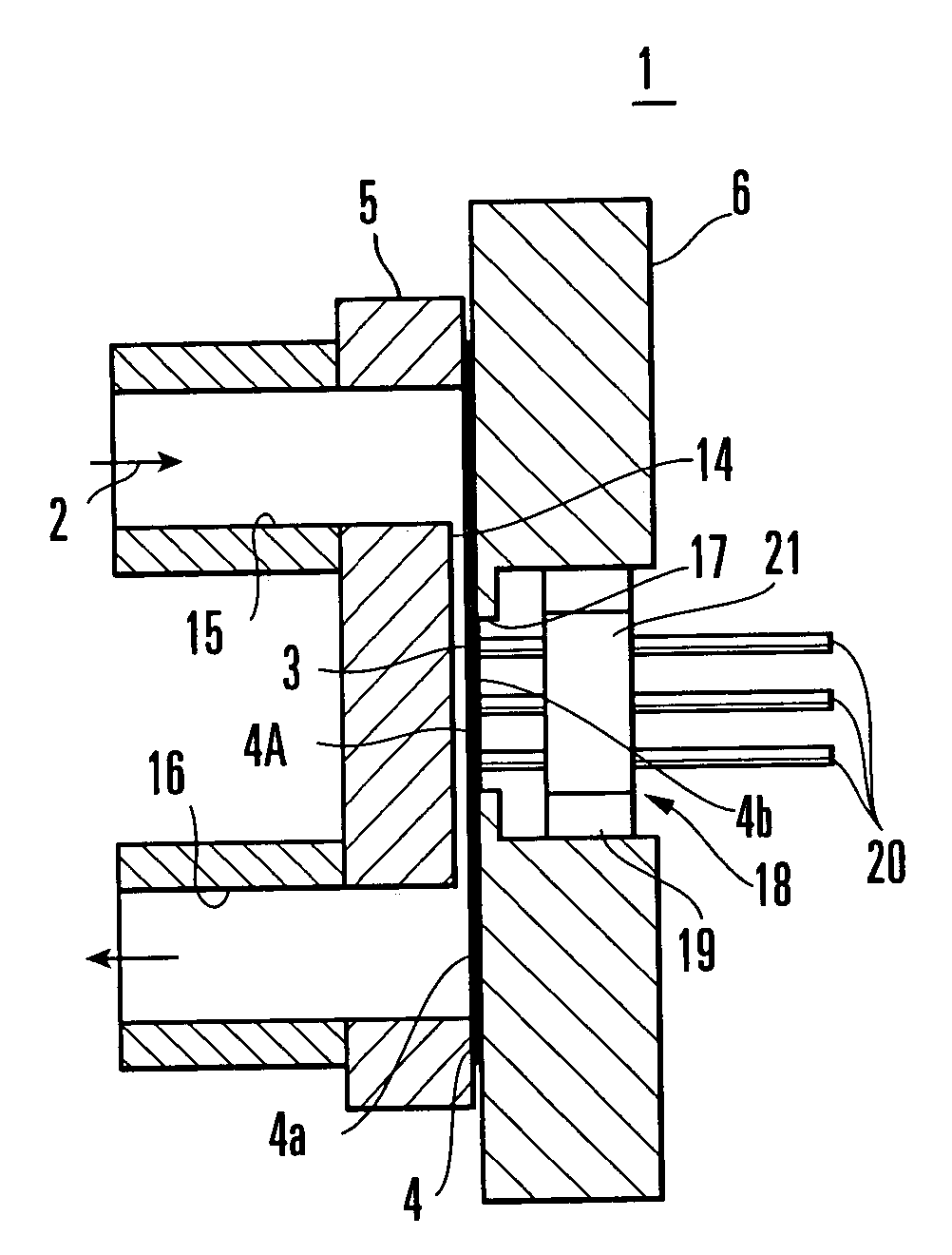
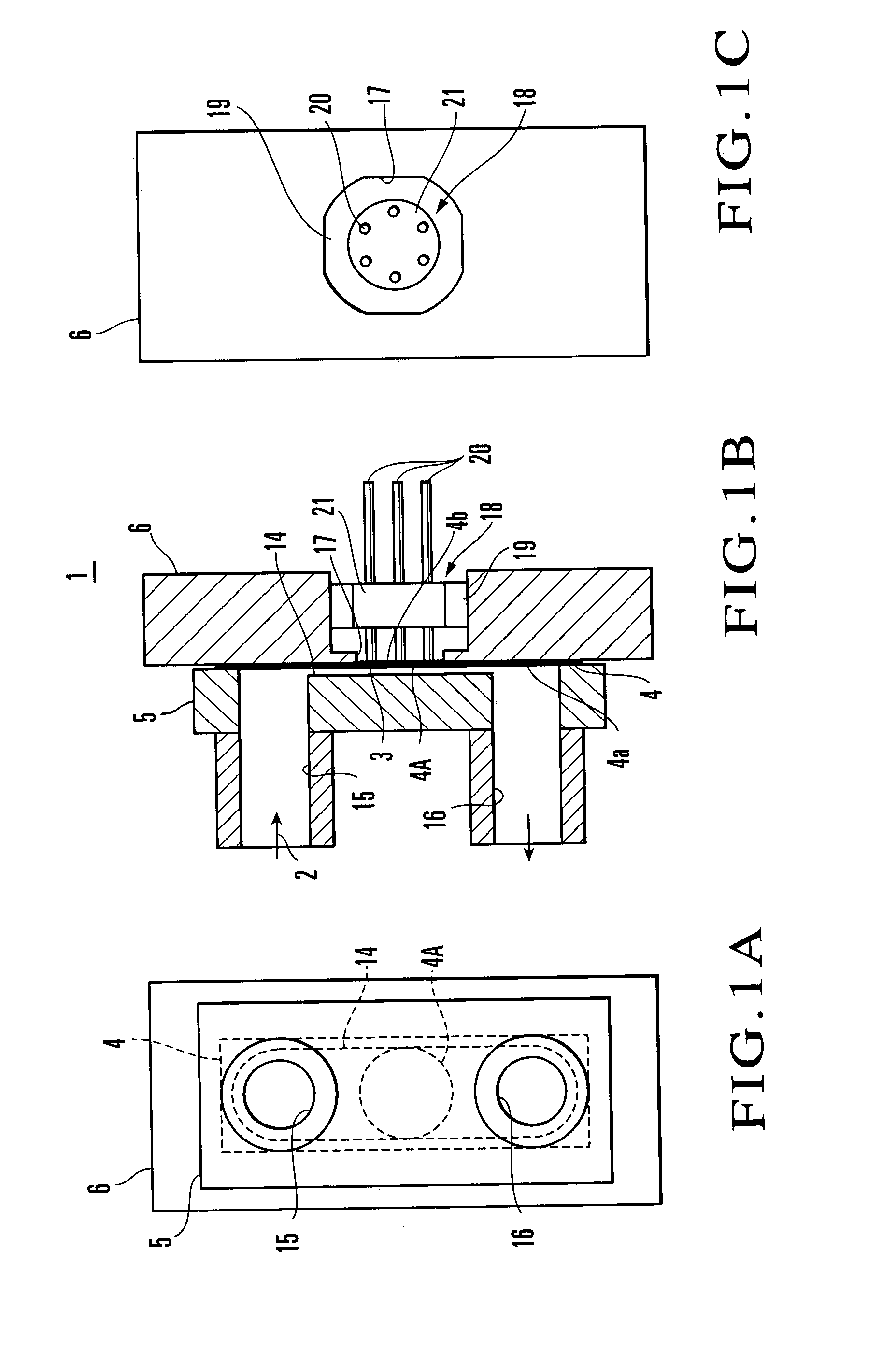
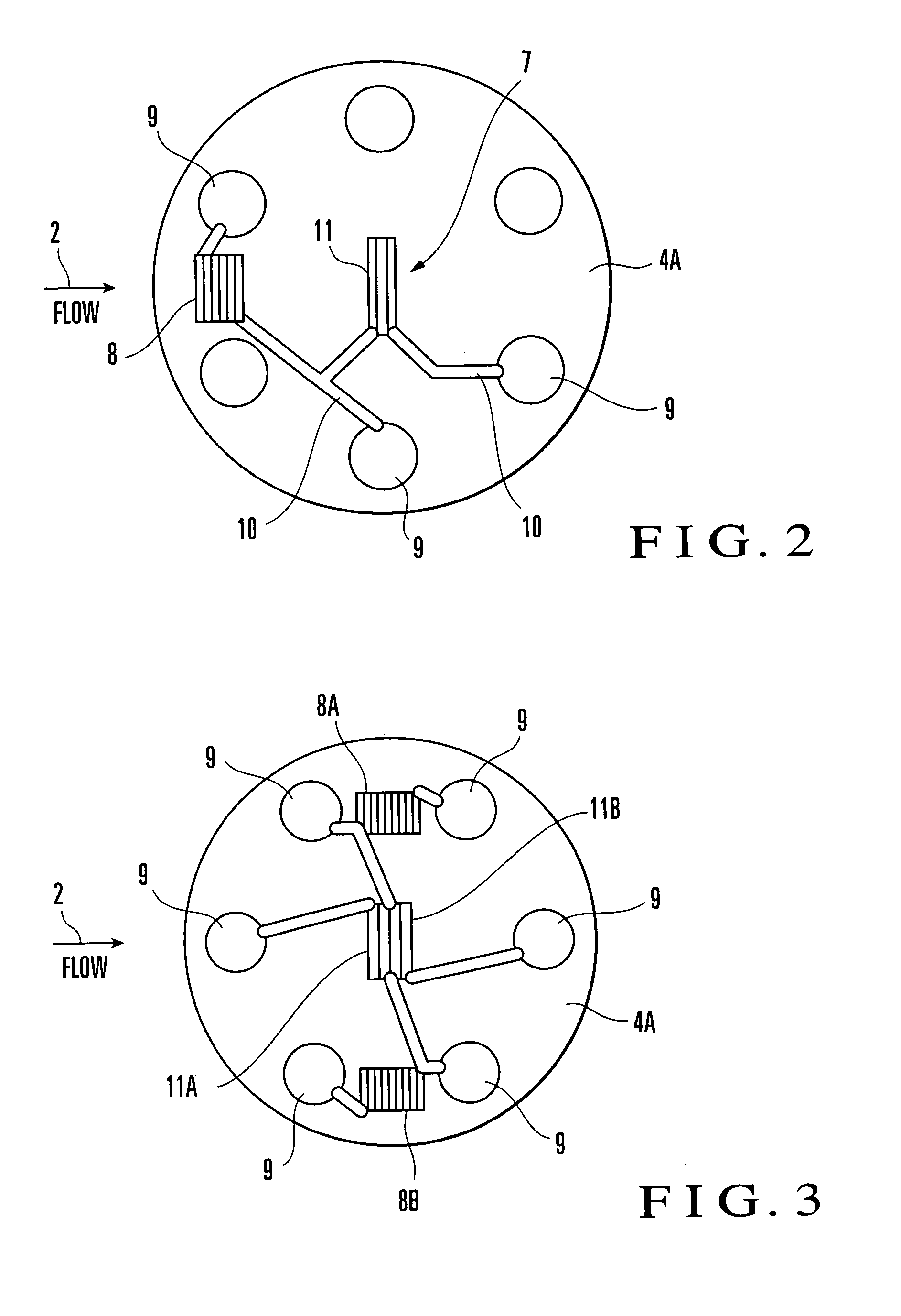
[0026]FIGS. 1A, 1B, and 1C are front, sectional, and rear views, respectively, showing a flow sensor according to an embodiment of the present invention, and FIG. 2 is a front view of a sensor portion. Referring to FIGS. 1A to 1C and FIG. 2, a flow sensor 1 is constituted by a substrate 4 having a front surface 4a side facing a channel 3 for a measurement target fluid (to be referred to as fluid hereinafter) 2, and a channel forming member 5 and a plate 6 disposed opposedly across the substrate 4. The substrate 4 and channel forming member 5 form a part of the channel 3. The channel forming member 5 and plate 6 are bonded to each other by welding or brazing, or with bolts.

[0027]The substrate 4 forms an elongated rectangular thin plate, and its peripheral portion is bonded to the rear surface of the channel forming member 5. As the material of the substrate 4, one having low thermal conductivity, h...


PUM


Abstract

A flow sensor (1) is constituted by a substrate (4) having a front surface (4a) side facing a channel (3) for a measurement target fluid (2), and a channel forming member (5) and a plate (6) disposed oppositely across the substrate (4). The substrate (4) is formed of stainless steel having a thickness of about 50 μm to 150 μm into a plate. An electric insulating film is formed on that surface (4b) of the substrate (4) which is opposite to the channel (3) side, and a temperature detection sensor (7) for measuring the flow velocity (flow rate) of the fluid (2), an ambient temperature sensor (8), an electrode pad (9), and a thin metal film (10) for wiring are formed on it.

Description

BACKGROUND ART[0001]The present invention relates to a flow sensor for measuring the flow velocity or flow rate of a fluid flowing in a channel and, more particularly, to a thermal flow sensor.[0002]Two types of flow sensors are known as thermal flow sensors for measuring the flow rate or flow velocity of a fluid. According to the first type, the spatial temperature distribution of a fluid is localized by the flow of heat emitted from a heat-generating body (heater), and the nonuniformity is detected by a temperature sensor (indirect heated type). According to the second type, a change in power or in resistance occurring when the heat of a heat-generating body is deprived of by a fluid is detected, thus detecting a flow velocity or flow rate (self-heating type).[0003]Conventionally, a flow sensor of this type is mainly used for a noncorrosive gas, and recently, one that can be used for liquid or a corrosive gas as well has been developed. For example, a flow rate sensor disclosed in...

Claims


Application Information

Patent Timeline
IPC IPC(8): G01F1/68G01F1/684G01F1/692
CPCG01F1/6842G01F1/6845G01F1/6847G01F1/692
Inventor KAMIUNTEN, SHOJIISHIKURA, YOSHIYUKIIKE, SHINICHIKINUGASA, SEIICHIROTANAKA, HIDEYUKI
Owner YAMATAKE HONEYWELL CO LTD
Learn More