Optical fiber tape core
a technology of optical fiber and core, applied in the field of optical fiber ribbon, can solve the problems of temporary increase in loss of optical fiber in use, adverse influence of loss on communication employing optical fiber, etc., and achieve the effects of reducing connection loss, excellent bending property, and high density
- Summary
- Abstract
- Description
- Claims
- Application Information
AI Technical Summary
Benefits of technology
Problems solved by technology
Method used
Image
Examples
embodiment 1
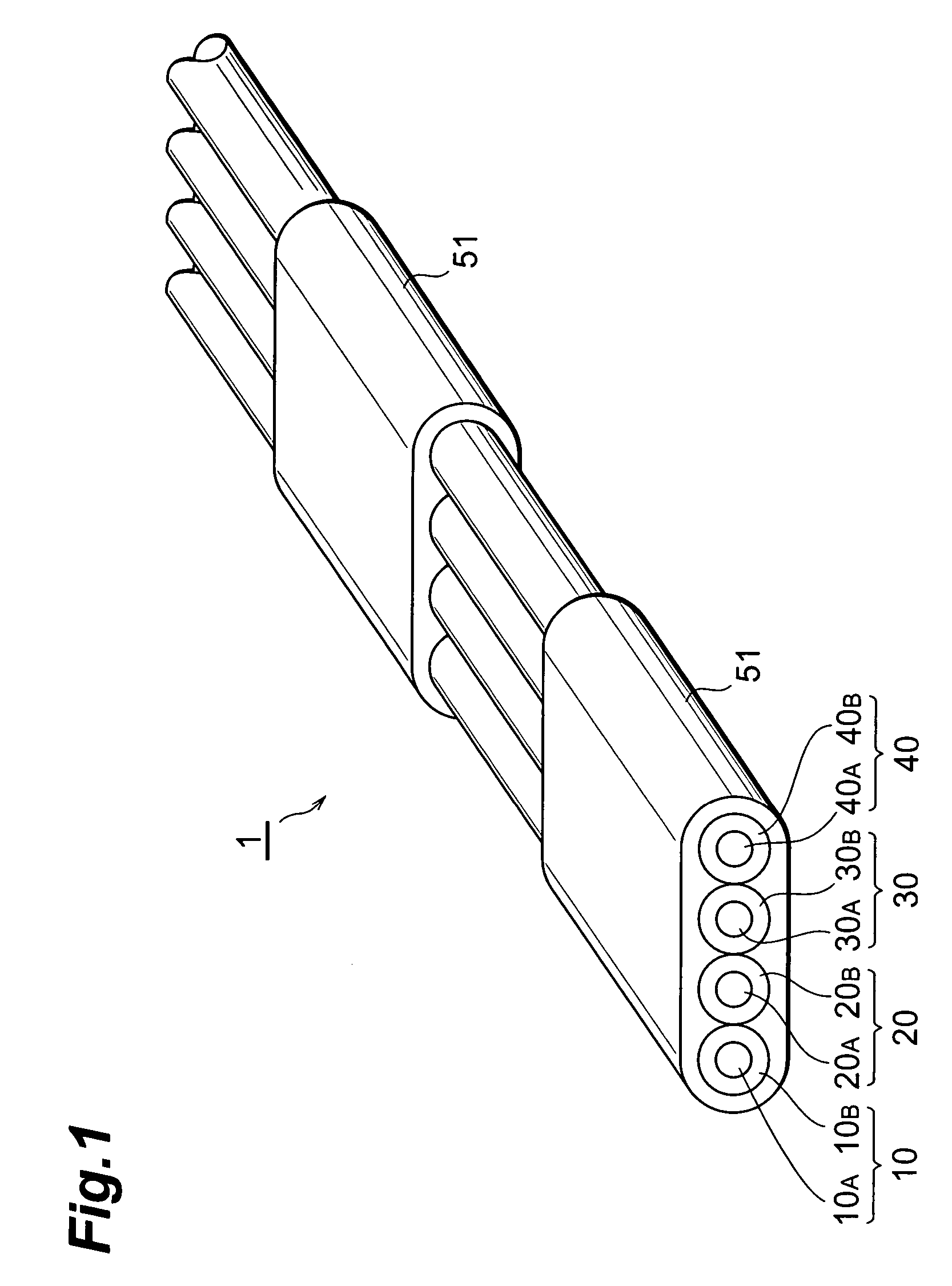
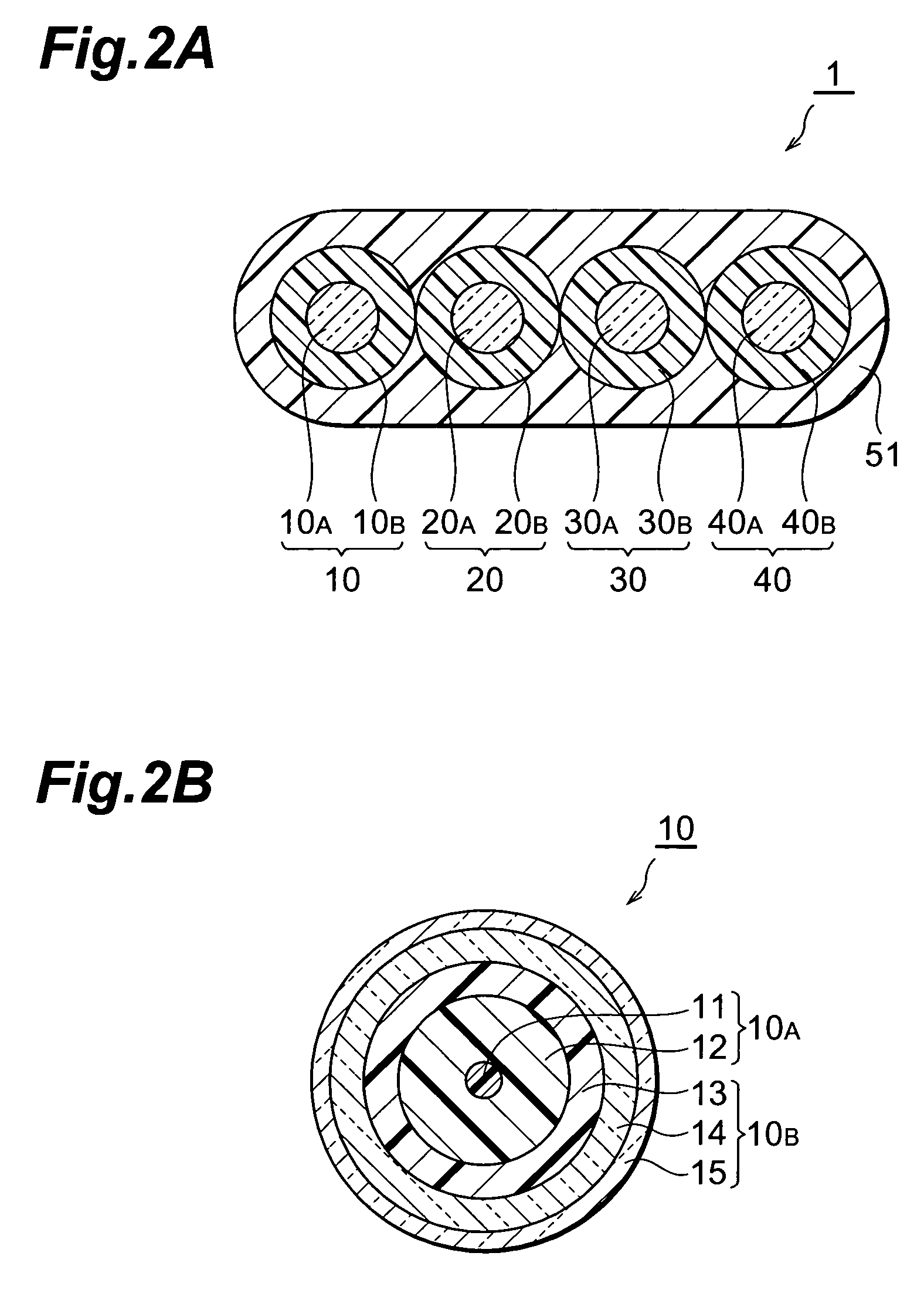
[0037]Particularly, in the optical fiber ribbon 1 , there alternate with each other first areas covered with the ribbon matrix 51 and second areas uncovered with the ribbon matrix along the longitudinal direction. The length in the longitudinal direction of the first areas and the second areas is preferably 10–300 mm. When the length of the first areas is shorter than 10 mm, there is a possibility that the ribbon matrix 51 is accidentally divided. When the length of the first areas is longer than 300 mm, it is hard to separate a single optical fiber. Also, when the length of the second areas is shorter than 10 mm, it is hard to separate a single optical fiber. When the length of the second areas is longer than 300 mm, there is a possibility that the ribbon matrix 51 is accidentally divided.
[0038]The ribbon matrix 51 is comprised of, for example, a UV curable resin, and the thickness thereof at the center of the optical fiber is preferably equal to the radius or less of each optical ...
embodiment 2
[0042]The optical fiber ribbon can be fabricated by applying the ribbon matrix by means of a coating die having a hole with a shape of section formed in such a manner that the thickness of the optical fiber ribbon becomes smaller in the position between the optical fibers each other.
[0043]FIG. 4 is a perspective view of an optical fiber ribbon 3 according to Embodiment 3. FIG. 5 is a sectional view of the optical fiber ribbon 3 according to the Embodiment 3. In the optical fiber ribbon 3, four optical fibers 10, 20, 30 and 40 are arranged in apparel in juxtaposition with each other in a certain plane, whereas a part of the periphery of the four optical fibers is covered with a ribbon matrix 53, but the rest thereof is not covered with the ribbon matrix. The ribbon matrix 53 is comprised of, for example, a UV curable resin, and the thickness thereof at the center of the optical fiber is preferably as large as the size of the radius of each optical fiber or less. Particularly, in the...
embodiment 4
[0046]The optical fiber ribbon can be formed by, immediately after the ribbon matrix is applied by a dispenser, removing the ribbon matrix in the sunken portions with a butt strap plate or the like, and then curing the remaining ribbon matrix.
[0047]FIG. 7 is a perspective view of an optical fiber ribbon 5 according to Embodiment 5. FIG. 8 is a sectional view of the optical fiber ribbon 5 according to the Embodiment 5. In the optical fiber ribbon 5, four optical fibers 10, 20, 30 and 40 are arranged in parallel to each other in a plane, and a part of the periphery of the four optical fibers is covered with a ribbon matrix 55, but the rest thereof is not covered with the ribbon matrix. The ribbon matrix 55 is comprised of, for example, a UV curable resin and the thickness thereof is preferably equal to the radius or less of each optical fiber. Particularly, the optical fiber ribbon 5 according to the Embodiment 5, first areas covered with the ribbon matrix 55 and second areas not cov...
PUM
 Abstract
Description
Claims
Application Information
 - R&D
- Intellectual Property
- Life Sciences
- Materials
- Tech Scout
- Unparalleled Data Quality
- Higher Quality Content
- 60% Fewer Hallucinations
Browse by: Latest US Patents, China's latest patents, Technical Efficacy Thesaurus, Application Domain, Technology Topic, Popular Technical Reports.
© 2025 PatSnap. All rights reserved.Legal|Privacy policy|Modern Slavery Act Transparency Statement|Sitemap|About US| Contact US: help@patsnap.com


