
Optical transducer having optical fiber plug transparent to curing light and non-transparent to sensing light

a technology of optical transducer and adhesive joint, which is applied in the direction of electrophonic musical instruments, counting objects on conveyors, instruments, etc., can solve the problems of insufficient cure of adhesive compound, insufficient adhesion, and prone to falling out of optical fiber bundles

Active Publication Date: 2006-10-03
YAMAHA CORP
View PDF4 Cites 11 Cited by
  • Summary
  • Abstract
  • Description
  • Claims
  • Application Information

AI Technical Summary

Benefits of technology

The present invention provides an optical transducer that accurately converts the current position of a moving object to an electric signal. The invention solves the problem of leakage light and insufficient adhesion by making the plugs of non-transparent synthetic resin and utilizing a holder with a plug portion made of synthetic resin that allows for the secure attachment of optical fibers through adhesive compound cured in a radiation of a curing light. The plug portion has a transmission sub-portion that allows the curing light to reach the adhesive compound and a prohibiting sub-portion that prevents leakage light from leaking through the ports. The technical effects of the invention are improved accuracy and reliability of optical transducers in converting physical quantities to electric signals.

Problems solved by technology

However, another problem was encountered in that the bundles of optical fibers were liable to fall out.
The reason why the bundles of optical fibers fell out was that the adhesive compound was insufficiently cured due to the shortage of the visible light.
Thus, there was a trade-off between the leakage light and the insufficient adhesion.

Method used


Image

  • Optical transducer having optical fiber plug transparent to curing light and non-transparent to sensing light
  • Optical transducer having optical fiber plug transparent to curing light and non-transparent to sensing light
  • Optical transducer having optical fiber plug transparent to curing light and non-transparent to sensing light

Examples


first embodiment

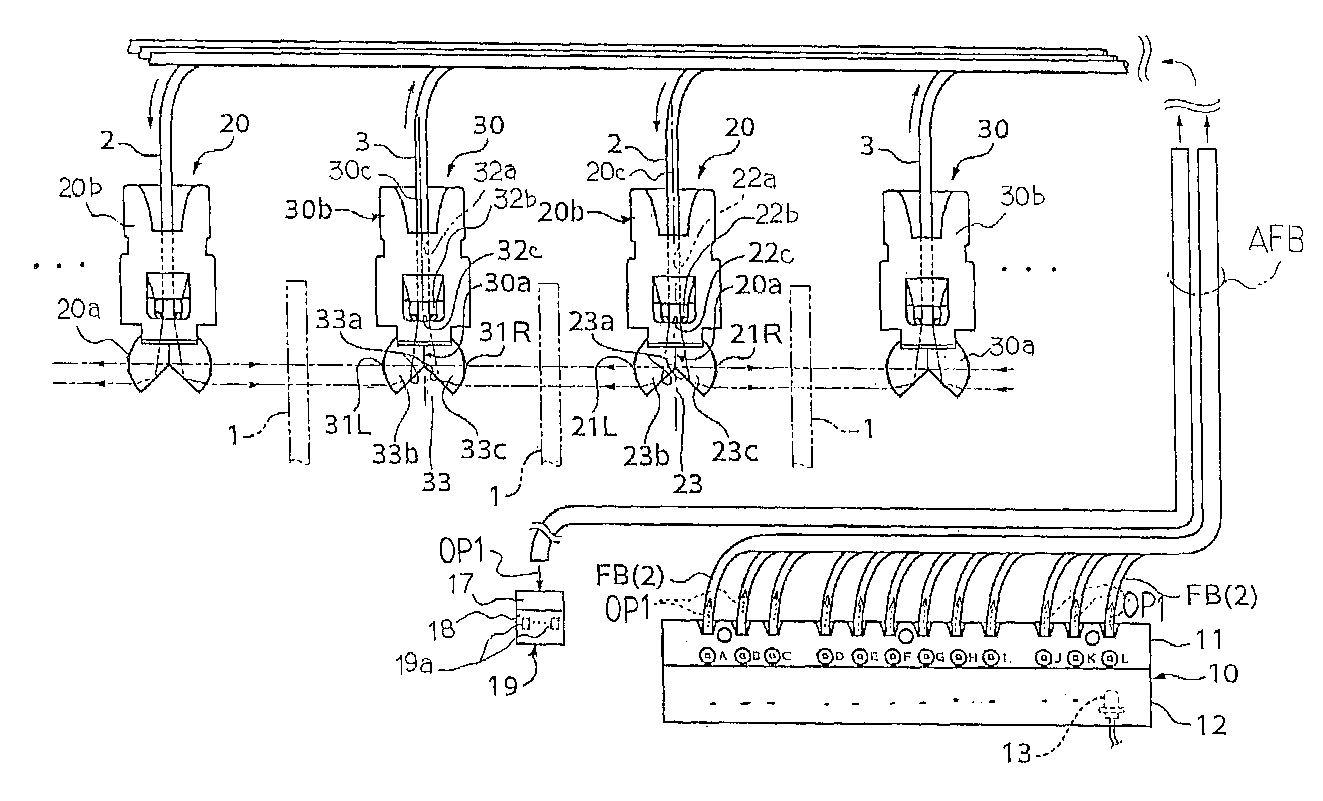
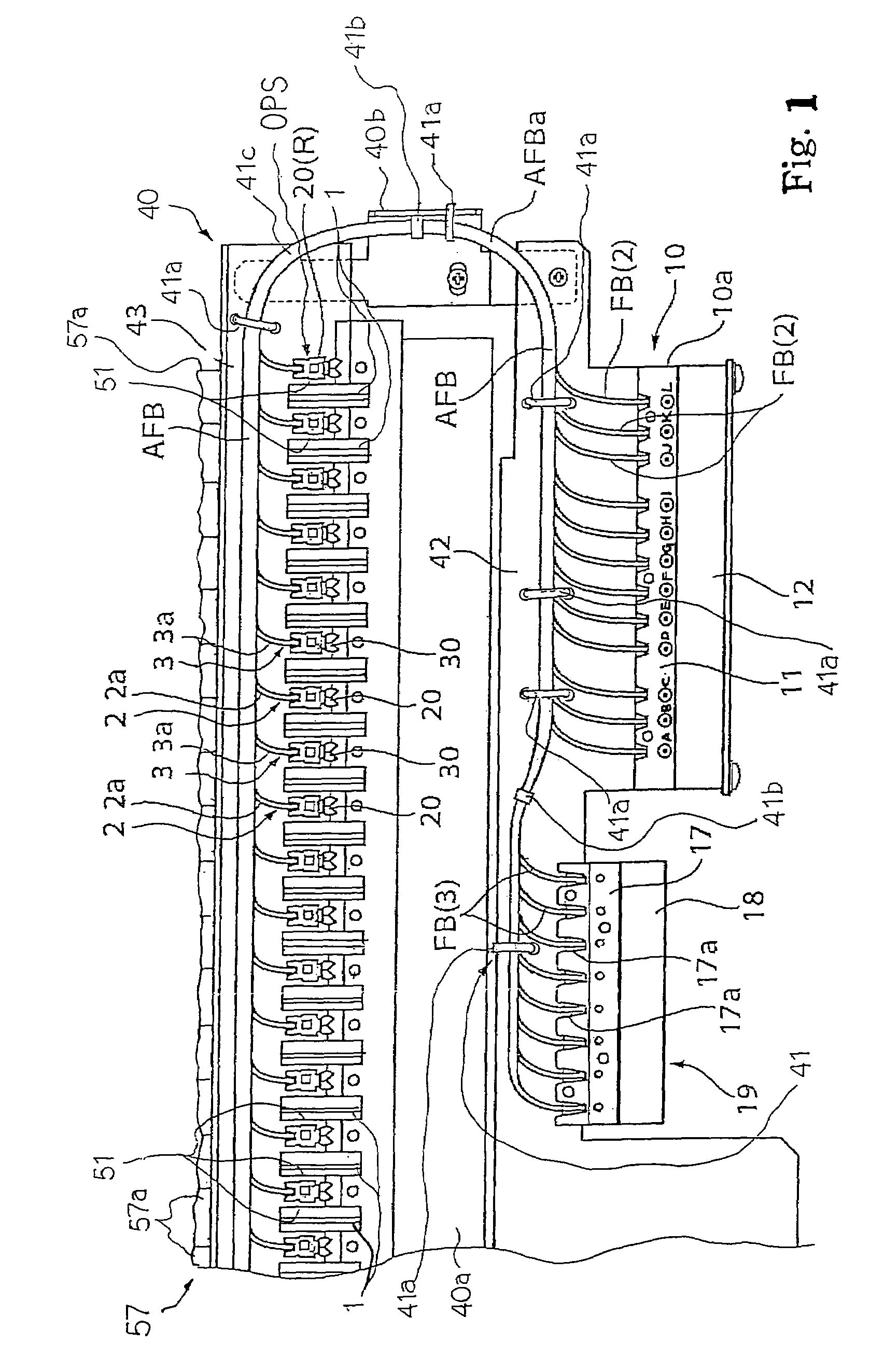
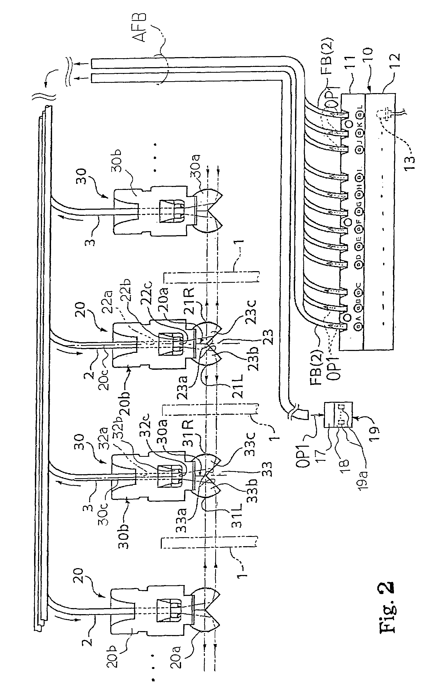
[0030]Referring to FIGS. 1 and 2 of the drawings, an optical transducer embodying the present invention largely comprises optical modulators 1 and a photo-electric converter OPS. The optical modulators 1 are respectively attached to moving objects such as, for example, keys 57a, which form parts of a keyboard 57 of an automatic player piano, and are moved together with the keys 57a. The photo-electric converter OPS radiates light beams across the optical modulators 1, and the light is modulated with the optical modulators 1 depending upon the current status of the keys 57a. In this instance, the current status means the positions of the keys 57a on the trajectories.

[0031]In the following description, terms “front” and “rear” are indicative of the relative positions, and the “front” is closer to a pianist who is fingering on a keyboard than the “rear”. A line drawn between a front position and a corresponding rear position extends in the “fore-and-aft direction”, and the fore-and-aft...

second embodiment

[0072]Referring to FIGS. 7, 8 and 9 of the drawings, an optical fiber plug 27 forms a part of a multi-port light detecting unit 29. The other parts of the multi-port light detecting unit 29 are similar to those of the multi-port light detecting unit 19. The multi-port light detecting unit 29 is incorporated in an optical transducer embodying the present invention, and the other component parts are similar to those of the optical transducer shown in FIG. 1. The other component parts of the optical transducer and other parts of the multi-port light detecting unit 29 are labeled with the references same as those designating the corresponding component parts of the optical transducer implementing the first embodiment. For this reason, description is hereinafter focused on the optical fiber plug 27.

[0073]The optical fiber plug 27 is formed with input ports 27a, which are respectively assigned to the minor bundles BF(3) of optical fibers. The input ports 27a are arranged in parallel to ea...


PUM


Abstract

An optical transducer includes a multi-port light emitting unit for distributing sensing light to minor bundles of optical fibers connected to input ports thereof and a multi-port light detecting unit for converting the sensing light to photo-current; an optical fiber plug, a socket and light detecting elements received in the socket are assembled in the multi-port light detecting unit; the optical fiber plug is made of semi-transparent colored synthetic resin, which is transparent to short-wavelength light and non-transparent to long-wavelength light, so that the minor bundles are adhered to the optical fiber plug through adhesive compound cured in the radiation of the short-wavelength light; the long-wavelength light serves as the sensing light so that leakage light does not reach the adjacent input ports.

Description

FIELD OF THE INVENTION[0001]This invention relates to an optical transducer and, more particularly, to an adhesive joint structure in an optical transducer.DESCRIPTION OF THE RELATED ART[0002]The optical transducer is a device that converts a non-electrical parameter, e.g. position, sound or pressure into electric signals through light. The optical transducers have found a wide variety of applications. One of the applicable technical fields is the musical instrument. The optical transducers are, by way of example, installed in the hybrid keyboard musical instrument. An automatic player piano and a mute piano are typical examples of the hybrid keyboard musical instrument, and the optical transducers convert the current position of moving objects such as keys and / or hammers to electric signals. The electric signals are supplied to a data processing system, and tones to be produced are determined through the analysis on the pieces of music data carried by the electric signals.[0003]A t...

Claims


Application Information

Patent Timeline
Patent Type & Authority Patents(United States)
IPC IPC(8): G02B6/00G06M7/00G10F1/02G10H1/055G10H1/34
CPCG10H1/0553G10H1/344G10H2220/411
Inventor KATO, TADAHARU
Owner YAMAHA CORP
Learn More