Nonvolatile semiconductor memory device and manufacturing method thereof
a nonvolatile, memory device technology, applied in the direction of semiconductor devices, electrical devices, transistors, etc., can solve the problems of increasing the amount of unerased electrons, the inability to secure the prescribed threshold voltage, and the inability to shorten the erasing time by leaps and bounds, so as to reduce the number of unerased electrons, improve rewriting durability, and reduce the influence of unerased and remaining electrons
- Summary
- Abstract
- Description
- Claims
- Application Information
AI Technical Summary
Benefits of technology
Problems solved by technology
Method used
Image
Examples
embodiments
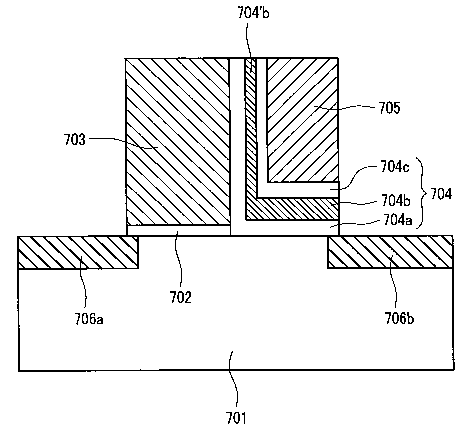
[0070]Next, the example of the first configuration explained earlier in FIG. 18 is explained concretely on the basis of the first and second embodiments, the example of the second configuration explained earlier in FIG. 19 on the basis of the third embodiment, and the example of the third configuration explained earlier in FIG. 20 on the basis of the fourth embodiment.
first embodiment
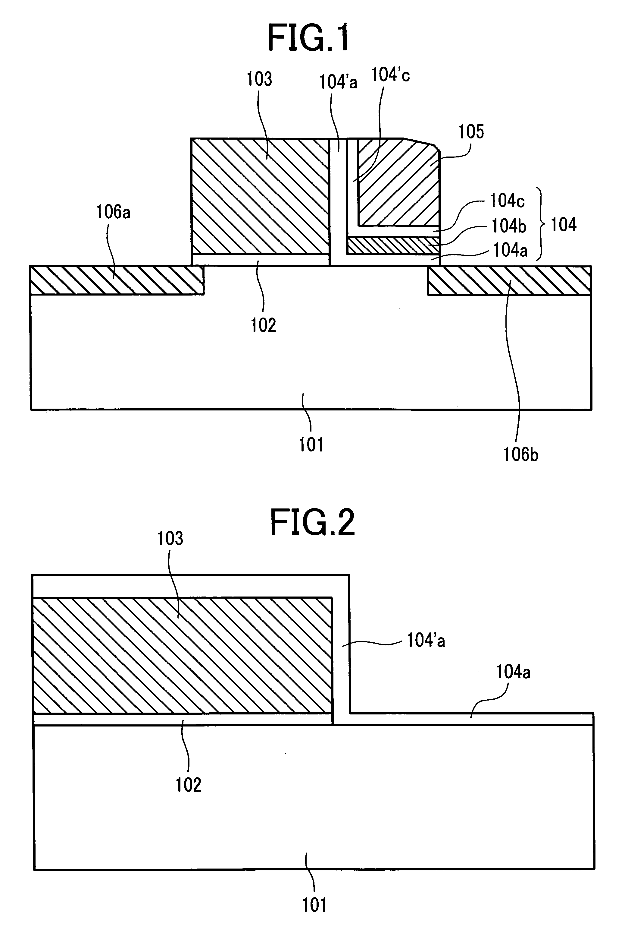
[0071]FIG. 1 is a sectional view of the first embodiment according to the present invention and corresponds to a sectional view taken on line X-Y of FIG. 7. The bit line 17 is expressed in FIG. 7 but not inFIG. 1.
[0072]The MONOS memory cell of a split gate structure produced in the present embodiment is composed of: a p-type well region (Si substrate) 101 formed on an Si substrate (semiconductor substrate); and two MOS transistors Q1 and Q2 having an n-type diffusion layer (n-type semiconductor region) acting as a source region 106a and another n-type diffusion layer acting as a drain region 106b, respectively.
[0073]The select MOS transistor Q2 is composed of an Si oxide film acting as a gate insulator film 102 and an n-type polycrystalline silicon film (hereunder referred to as “Si film”) acting as a select gate electrode (electric conductor) 103.
[0074]The memory MOS transistor Q1 is composed of: an Si oxide film acting as a lower layer potential barrier film 104a isolating the p-t...
second embodiment
[0095]Next, the second embodiment according to the present invention is explained on the basis of FIGS. 21 to 26. In the embodiment, in the same way as the first embodiment, three other methods wherein an Si nitride film acting as a charge trapping film was not formed at the sidewall bottom portion of the select gate electrode were investigated. The obtained results are hereunder explained sequentially.
[0096](1) The First Method
[0097]The method is explained on the basis of FIGS. 21 and 22. Firstly, as shown by the sectional view of FIG. 21, the gate insulator film 802 of the select MOS transistor Q2 was formed on the Si substrate 801 in the same way as the first embodiment, and thereafter the non-doped polycrystalline Si film 803 200 nm in thickness was deposited.
[0098]Successively, phosphor was injected by 8e15 atms / cm2 into the region 803″ about 100 nm distant from the surface of the polycrystalline Si film 803 acting as the select gate electrode 803 by the ion implantation method...
PUM
 Abstract
Description
Claims
Application Information
 - R&D
- Intellectual Property
- Life Sciences
- Materials
- Tech Scout
- Unparalleled Data Quality
- Higher Quality Content
- 60% Fewer Hallucinations
Browse by: Latest US Patents, China's latest patents, Technical Efficacy Thesaurus, Application Domain, Technology Topic, Popular Technical Reports.
© 2025 PatSnap. All rights reserved.Legal|Privacy policy|Modern Slavery Act Transparency Statement|Sitemap|About US| Contact US: help@patsnap.com


