Optical information storage medium and recording/reproducing method for the optical information storage medium
a technology of optical information storage and optical information, which is applied in the field of optical information storage medium and recording/reproducing method thereof, can solve the problems of damage to user data, drive for high-speed disc can also damage user data, and the recording speed of a disc cannot reach the nominal recording speed, so as to achieve the effect of not damaging the user
- Summary
- Abstract
- Description
- Claims
- Application Information
AI Technical Summary
Benefits of technology
Problems solved by technology
Method used
Image
Examples
first embodiment
[0036]In a recording / reproducing method for an optical information storage medium according to the present invention, a maximum recordable speed is recorded in a recordable zone of the areas other than the user data area. For example, the maximum recordable speed information can be recorded in a predetermined area of the re-recordable data zone 30. Meanwhile, the maximum recordable speed information, which is data reproduced using the sum channel (ch1), can be recorded in the same manner as data is recorded in the user data area.
[0037]For example, FIG. 2 shows a predetermined area of the re-recordable data zone 30 having a plurality of bytes. As shown in FIG. 2, the predetermined area can store the maximum recordable speed information in one byte among the plurality of bytes. That is, the re-recordable data zone 30 stores a recordable speed flag or a recordable speed code using at least one bit existing at a zero byte position (BP) 35 in the predetermined area or using a bit combina...
second embodiment
[0047]In a recording / reproducing method for an optical information recording medium according to the present invention, the maximum recordable speed is recorded in all of the bits that constitute a recordable zone of areas other than a user data area. For example, the maximum speed information can be recorded in a predetermined area of the re-recordable data zone 30. Here, the re-recordable data zone 30 is also included in a lead-out area.
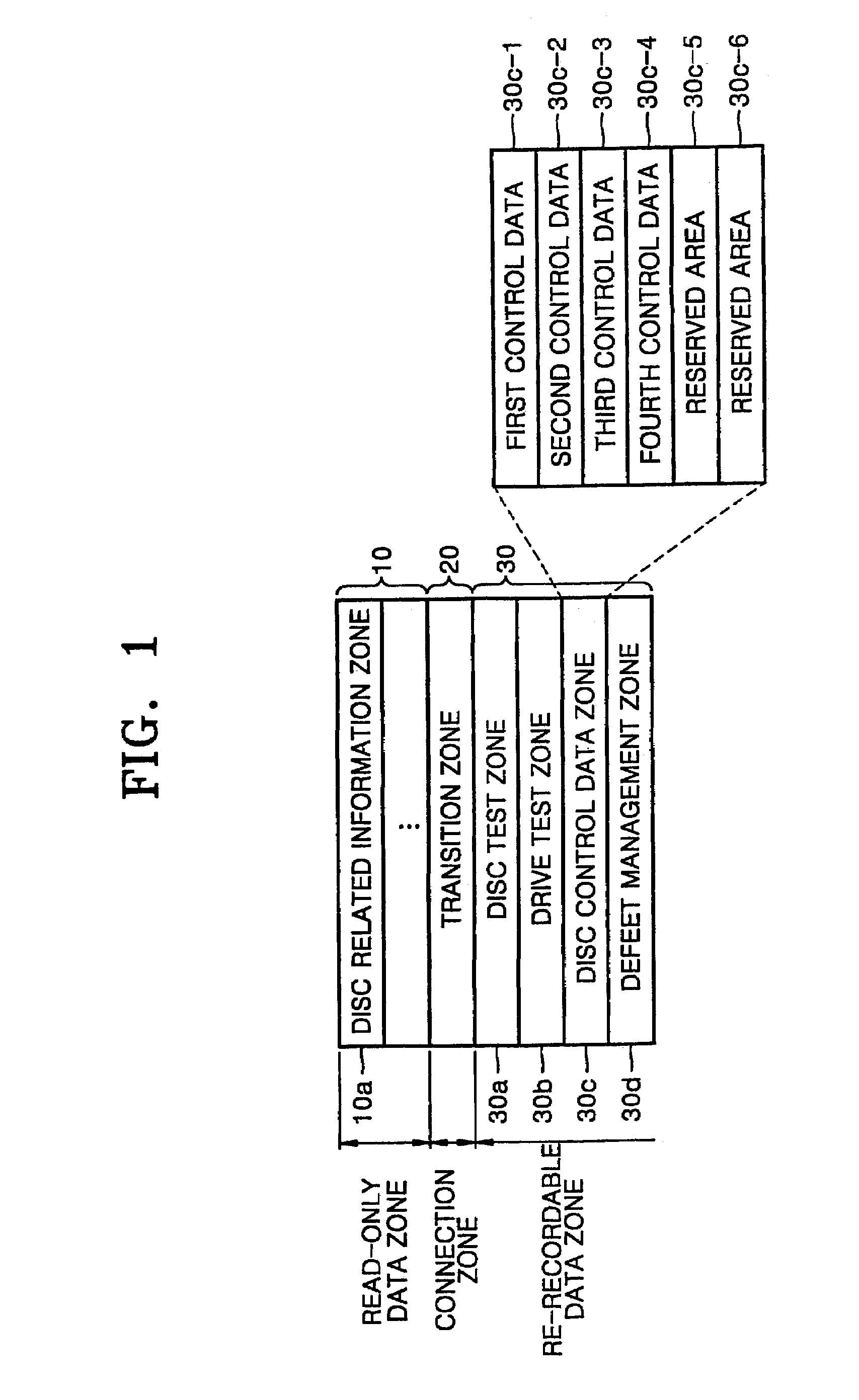
[0048]That is, maximum and minimum recordable speed information can be recorded in a predetermined area, for example, either the disc control data areas 30c-1, 30c-2, 30c-3, and 30c-4 or the reserved areas 30c-5 and 30c-6, in the re-recordable data zone 30. As shown in FIG. 3B, either the disc control data areas 30c-1, 30c-2, 30c-3 and 30c-4, or the reserved areas 30c-5 and 30c-6 comprise a plurality of bytes. The maximum and minimum recordable speed information is recorded using, for example, all of the 8 bits that constitute each byte. Here, the ...
third embodiment
[0054]An optical information storage medium according to the present invention and a recording / reproducing method thereof will now be described with reference to FIGS. 1 and 4.
[0055]In this embodiment, a recordable speed is recorded in a predetermined area of a re-recordable area of at least one of lead-in and lead-out areas by using each bit.
[0056]For example, recordable speed information can be recorded in the disc control data area 30c-1, 30c-2, 30c-3, 30c-5 or the reserved area 30c-5, 30c-6, using a bit or a combination of bits in a predetermined area of the re-recordable data zone 30 shown in FIG. 1. The disc control data area 30c-1, 30c-2, 30c-3, 30c-5 and the reserved area 30c-5, 30c-6 comprise a plurality of bytes, and the recordable speed is recorded by using, for example, 8 bits of one byte of the plurality of bytes.
[0057]That is, each bit of a BP corresponds to different recordable speeds, and corresponding recordable speed information is recorded by using each bit. For e...
PUM
| Property | Measurement | Unit |
|---|---|---|
| recording speed | aaaaa | aaaaa |
| recordable speed | aaaaa | aaaaa |
| speed | aaaaa | aaaaa |
Abstract
Description
Claims
Application Information
 - R&D
- Intellectual Property
- Life Sciences
- Materials
- Tech Scout
- Unparalleled Data Quality
- Higher Quality Content
- 60% Fewer Hallucinations
Browse by: Latest US Patents, China's latest patents, Technical Efficacy Thesaurus, Application Domain, Technology Topic, Popular Technical Reports.
© 2025 PatSnap. All rights reserved.Legal|Privacy policy|Modern Slavery Act Transparency Statement|Sitemap|About US| Contact US: help@patsnap.com


