
Design and fabrication methodology for a phased array antenna with integrated feed structure-conformal load-bearing concept

a phased array antenna and feed structure technology, applied in the field of antenna systems, can solve the problems of no function and special requirements, and achieve the effects of avoiding parasitic weight, providing structural strength, and facilitating electrical connection of radiating elements

Active Publication Date: 2006-09-26
THE BOEING CO
View PDF8 Cites 32 Cited by
  • Summary
  • Abstract
  • Description
  • Claims
  • Application Information

AI Technical Summary

Benefits of technology

The present invention is about an antenna aperture that can be integrated into a mobile platform, such as an aircraft or spacecraft, as a structural load bearing portion. It is made up of a honeycomb-like grid of antenna elements sandwiched between two panels, which provides the necessary strength. The antenna aperture can be manufactured and scaled to different applications. It can be shaped to match the outer mold line of the structure and can include a plurality of independent antenna apertures. The invention allows for the integration of a large number of antenna radiating elements into a non-linear mold line of a structure. The technical effects of the invention include improved structural strength, reduced weight, and improved electrical performance.

Problems solved by technology

Often these components comprise aluminum blocks or other like substructures that add “parasitic” weight to the overall antenna aperture, but otherwise perform no function other than as a support structure for a portion of the antenna aperture.
This requirement becomes especially challenging when the antenna system is required to incorporate a large number of antenna elements that must be integrated into an area having a curving or otherwise non-linear contour.

Method used


Image

  • Design and fabrication methodology for a phased array antenna with integrated feed structure-conformal load-bearing concept
  • Design and fabrication methodology for a phased array antenna with integrated feed structure-conformal load-bearing concept
  • Design and fabrication methodology for a phased array antenna with integrated feed structure-conformal load-bearing concept

Examples


Embodiment Construction

[0083]The following description of the preferred embodiment(s) is merely exemplary in nature and is in no way intended to limit the invention, its application, or uses.

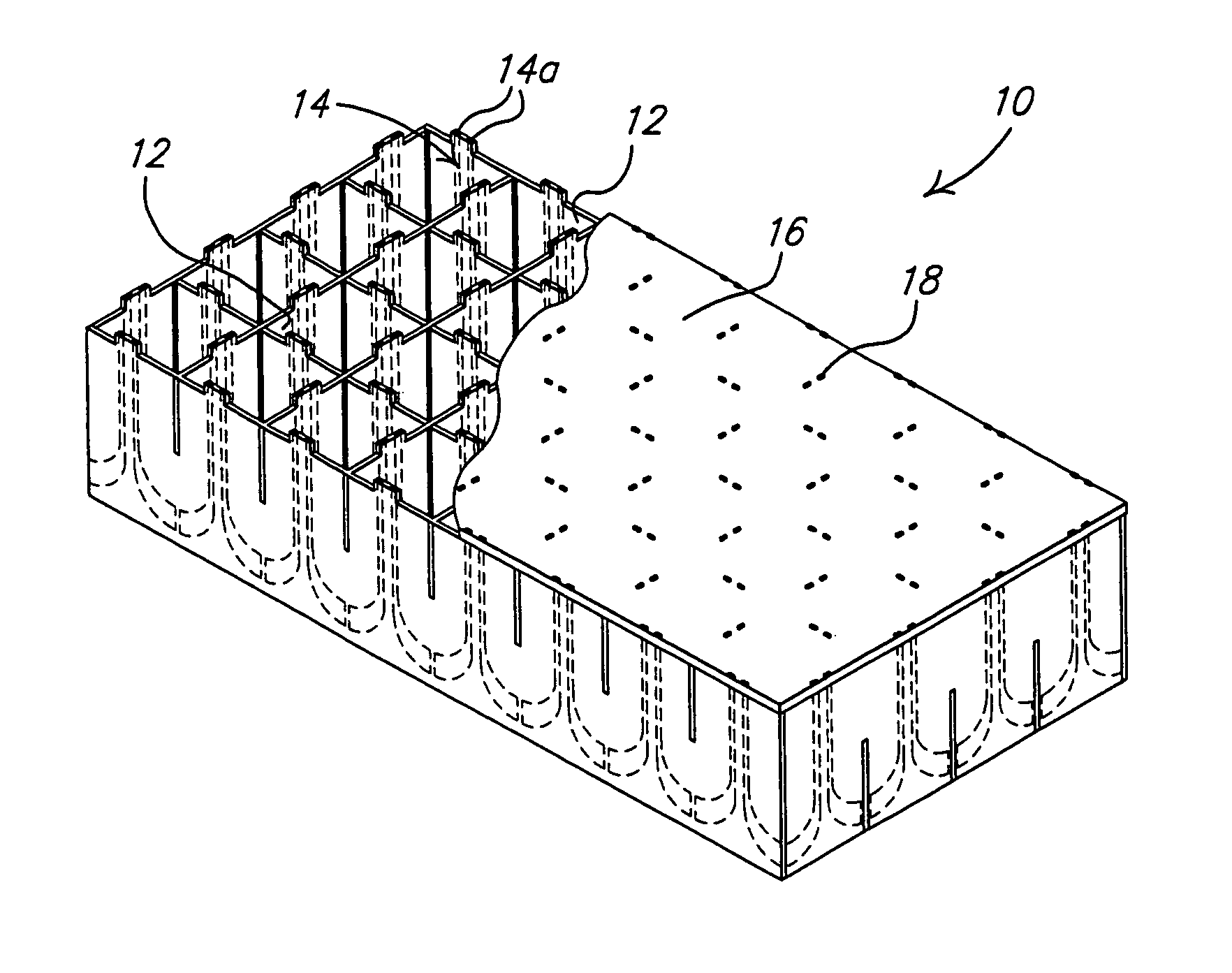
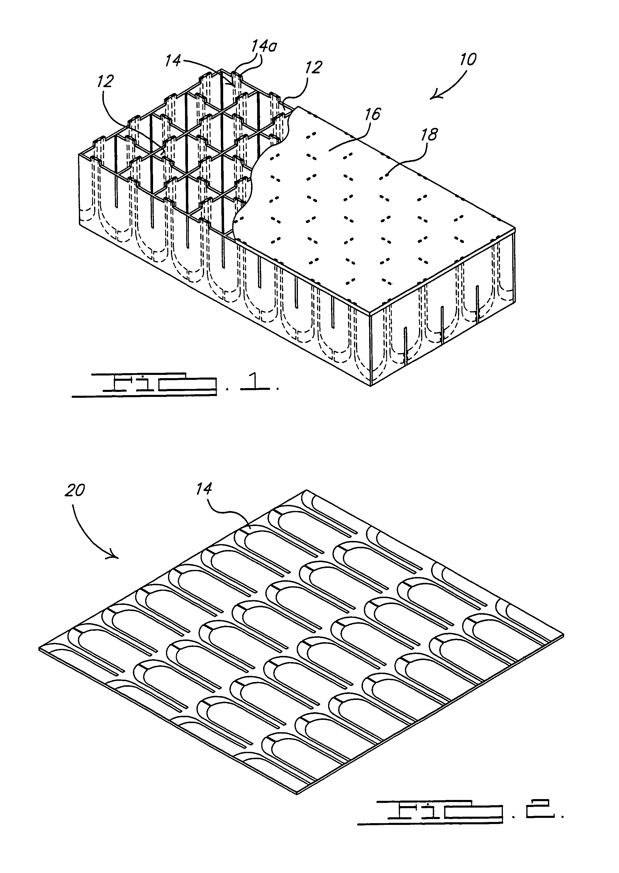
[0084]Referring to FIG. 1, there is shown an antenna aperture 10 in accordance with a preferred embodiment of the present invention. The antenna aperture 10 essentially forms a load bearing honeycomb-like structure that can be readily integrated into composite structural portions of mobile platforms without affecting the overall strength of the structural portion, and without adding significant additional weight beyond what would be present with a conventional honeycomb core, sandwich-like construction technique that does not incorporate an antenna capability.

[0085]The aperture 10 includes a plurality of wall sections 12 interconnected to form a honeycomb or grid-like core section. Each wall section 12 includes a plurality of electromagnetic radiating elements 14 embedded therein. While FIG. 1 illustrates an X-Y grid-...


PUM


Abstract

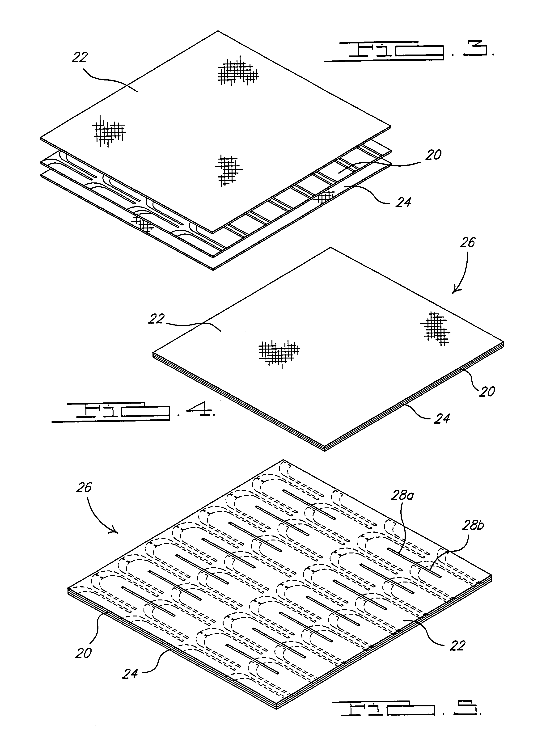
A conformal, load bearing, phased array antenna system having a plurality of adjacently positioned antenna aperture sections that collectively form a single, enlarged antenna aperture. The aperture sections are each formed by intersecting wall panels that form a honeycomb-like core having a plurality of electromagnetic radiating elements embedded in the wall panels that form the core. The aperture wall panels are assembled onto a single, multi-faceted back skin, bonded thereto, and then machined to produce a desired surface contour. A radome formed by a single piece of composite material is then bonded to the contoured surface. Antenna electronics printed wiring boards are also bonded to an opposite side of the back skin. The contour is selected to match a mold line of a surface into which the antenna system is installed. The antenna is able to form an integral, load bearing portion of the structure into which it is installed.

Description

STATEMENT OF GOVERNMENT RIGHTS[0001]This invention was made with Government support under Contract Number F33615-97-2-3220 awarded by the United States Air Force. The U.S. Government has certain rights in this invention.CROSS REFERENCE TO RELATED APPLICATIONS[0002]This application includes subject matter related to the following U.S. applications filed concurrently with, the present application: Ser. No. 10 / 970,702 Ser. No. 10 / 970 703 now U.S. Pat. No. 7,046,209 and Ser. No. 10 / 970,710 all of which are incorporated by reference into the present application.FIELD OF THE INVENTION[0003]The present invention relates to antenna systems, and more particularly to a conformal antenna system having a plurality of antenna apertures formed adjacent one another, and having a desired contour. The antenna system can be used as a structural, load-bearing portion of a mobile platform and constructed to match an outer mold line of the area of the mobile platform into which the antenna system is int...

Claims


Application Information

Patent Timeline
Patent Type & Authority Patents(United States)
IPC IPC(8): H01Q21/26H01Q1/40H01Q1/28H01Q21/00H01Q21/06
CPCH01Q1/286H01Q21/062H01Q21/0087H01Q1/27
Inventor MCCARVILLE, DOUGLAS AHERNDON, GERALD FMARSHALL, IV, JOSEPH AVOS, ROBERT GBANKS, DAVID L
Owner THE BOEING CO
Learn More