
Connector assembly for printed circuit board interconnection

a technology of printed circuit board and connector assembly, which is applied in the direction of printed circuits, electrical devices, connections, etc., can solve the problems of complicated mounting mechanism, high cost of conventional connector design, and inability to meet electronic components in compact arranged intermediate circuit boards. , to achieve the effect of simplifying the installation process and reducing the number of interconnection interfaces

Inactive Publication Date: 2006-09-26
HON HAI PRECISION IND CO LTD
View PDF7 Cites 17 Cited by
  • Summary
  • Abstract
  • Description
  • Claims
  • Application Information

AI Technical Summary

Benefits of technology

[0007]Therefore, an object of the present invention is to provide a connector assembly having the least connector parts to electrically connect a primary circuit board to other intermediate circuit boards / extension cards in a backplane application so as to reduce the number of needed interconnecting interfaces of the connector assembly and simplify the installation process of the connector.
[0008]Another object of the present invention is to provide a connector assembly having a simplified mounting mechanism to circuit boards to effectively save the occupied space of the circuit boards where the connector assembly is seated respectively.
[0009]Another object of the present invention is to provide a connector assembly having conductors with a consistent mechanism and engaging method, therefore all of the conductors can be easily made by similar producing processes to reduce the cost of manufacturing.
[0010]To obtain the above objects, a connector assembly in accordance with the present invention includes a one-piece insulated housing and an outer shell partially enclosing outside of the housing. The housing has a space formed from a mounting side of the housing toward the primary circuit board and a face formed at another mounting side of the housing toward the intermediate circuit board. A plurality of conductors is retained in the housing and extends from the space to the face and each conductor has one tail portion to be press-fit on the intermediate circuit board and another tail portion to be engaged with a corresponding hole on the primary circuit board. The one-piece housing and fewer interfaces of the connector assembly are used, and the mounting method and mechanism of the conductors is simplified to reduce the cost of manufacturing.
[0012]Another embodiment of a connector assembly in accordance with the present invention comprises at least two connector parts. Each connector part has a plurality of conductors installed therein, and conductors of different connector parts are adapted to be mounted onto the circuit boards or mated with each other in a similar way and mechanism. The manufacturing cost of conductors of the connector assembly can be effectively reduced.

Problems solved by technology

Therefore, the conventional connector designs will have a high cost for the type of application.
Additionally, in the compact arrangement of the intermediate circuit board, limited space is available to receive electronic components and smaller pitches between contacts restrain possible variations of size and shape of the connectors of their parts, especially the intermediate circuit board having lots of extension cards installed thereon.
Obviously, complicated mating of mounting mechanism the conventional plug and receptacle connectors have is not the best choice for a compact arranged intermediate circuit board.

Method used


Image

  • Connector assembly for printed circuit board interconnection
  • Connector assembly for printed circuit board interconnection
  • Connector assembly for printed circuit board interconnection

Examples


Embodiment Construction

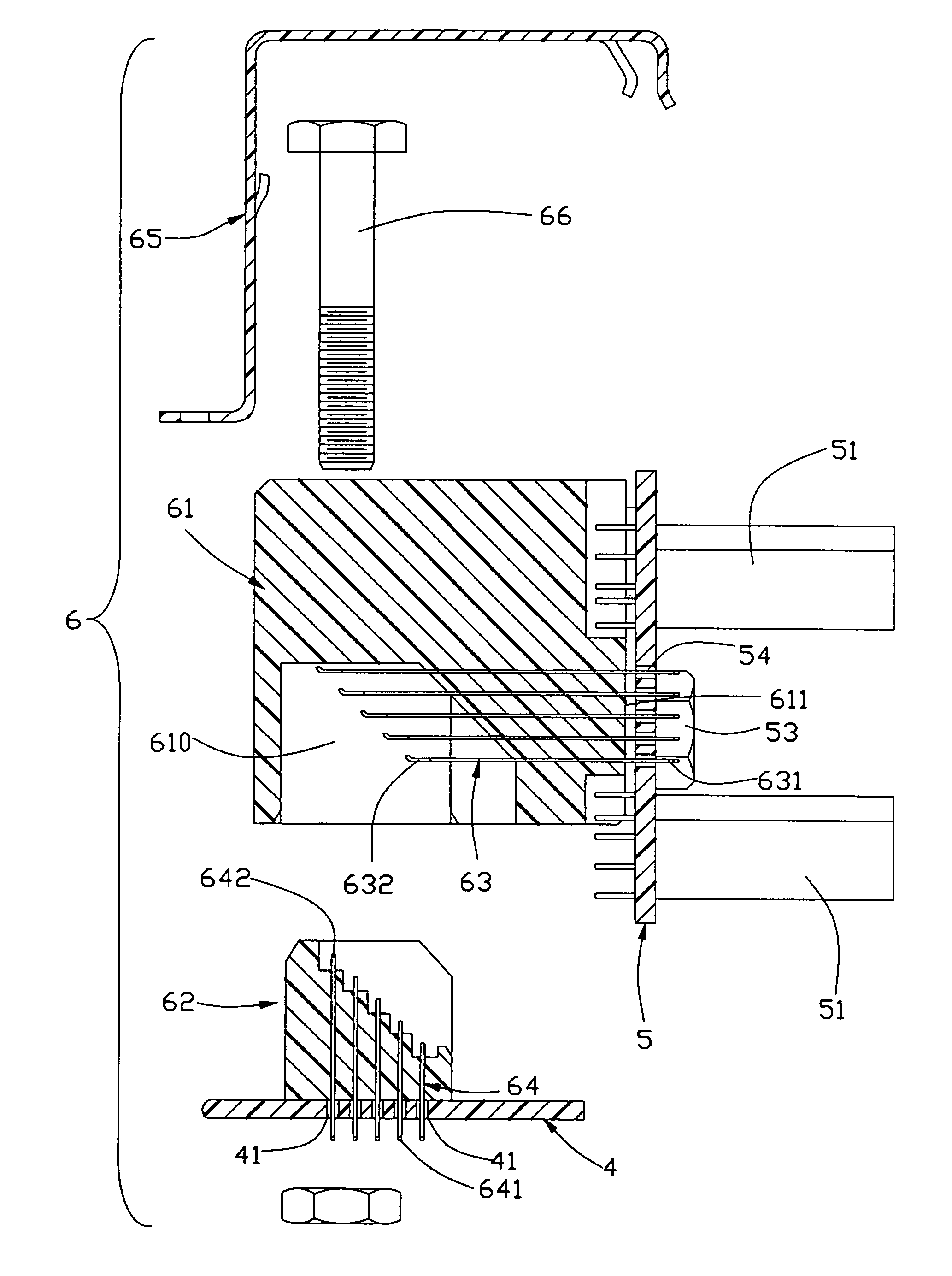
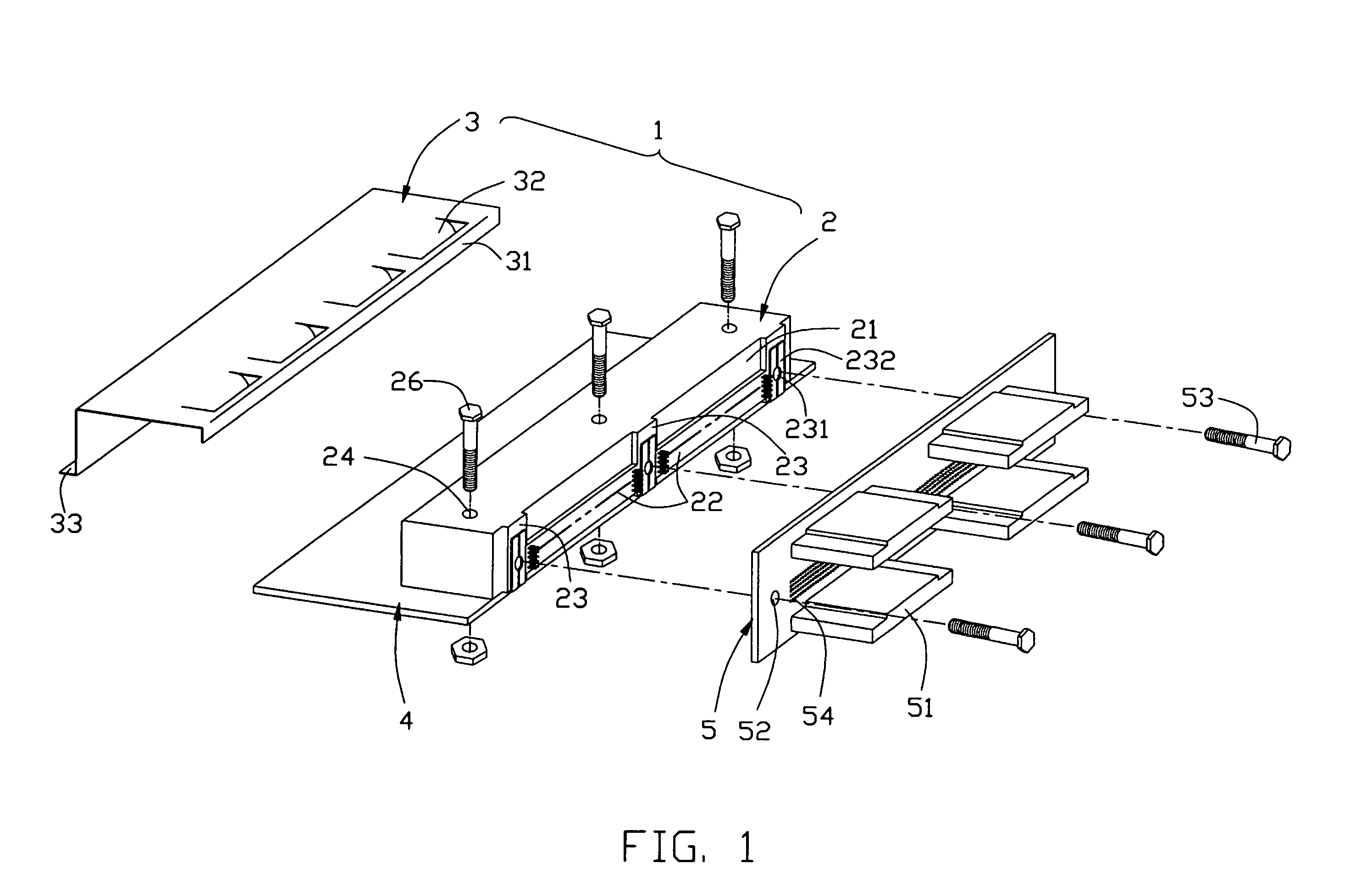
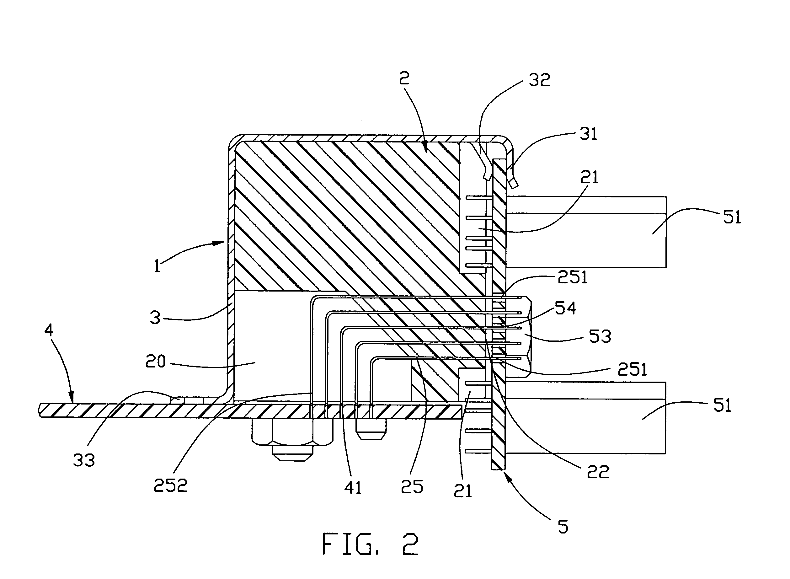
[0022]Referring to FIGS. 1 and 2, the connector assembly 1 in accordance with a first embodiment of the present invention is shown to be seated on a primary circuit board 4 of a backplane assembly and be going to be mounted on an intermediate (secondary) circuit board 5 having a plurality of connectors 51 disposed thereon to electrically connect with corresponding extension cards (not shown). The connector assembly 1 includes an insulated housing 2 and an outer shell 3 enclosing outside of the housing 2. The housing 2 has a first side abutting against the surface of the primary circuit board 4 when the connector assembly 1 is seated on the board 4. A space 20 is formed inside the housing 2 and has an opening formed on the first side. Meanwhile, a face 22 having a plurality of holes formed thereon is located at a second side of the housing 2 neighboring the first side. Recesses 21 are formed at the second side of the housing 2 next to the face 22. And several protrusions 23 extending...


PUM


Abstract

A connector assembly (1) used to interconnect a primary circuit board (4) to an intermediate circuit board (5) includes a one-piece insulated housing (2) and an outer shell (3) partially enclosing outside of the housing (2). The housing (2) has a space (20) formed from a mounting side of the housing (2) to the primary circuit board (4) and a face (22) formed at another mounting side of the housing (2) to the intermediate circuit board (5). A plurality of conductors (25) is retained in the housing and extends from the space (20) to the face (22) and each conductor (25) has one tail portion (251) to be press-fit on the intermediate circuit board (5) and another tail portion to be engaged with a corresponding hole (41) on the primary circuit board (4). The one-piece housing and fewer interfaces are used, and the mounting method and mechanism of the conductors is simplified to reduce the cost of manufacturing.

Description

CROSS-REFERENCE TO RELATED APPLICATION[0001]This application is related to U.S. patent application Ser. No. 10 / 318,502, filed Dec. 12, 2002.BACKGROUND OF THE INVENTION[0002]1. Field of the Invention[0003]The present invention is related to a connector assembly having contacts with high density arrangement so as to interconnect two printed circuit boards or modularized circuit board assemblies, especially to a connector assembly having a simple and facilely assembled mounting interface for connecting daughter board assembly to a motherboard.[0004]2. Description of Prior Arts[0005]In a specialized backplane assembly of a computation or communication device, a primary circuit board is used to connect other intermediate circuit boards or extension cards to achieve different electronic functions or performance. In most situations, more extension cards are needed to connect to the primary circuit board via one of the intermediate (secondary) circuit boards / extension cards in order to prov...

Claims


Application Information

Patent Timeline
IPC IPC(8): H01R12/00
CPCH01R12/7047H01R12/52
Inventor KORSUNSKY, IOSIF R.SHIPE, JOANNE E.HYLAND, JAMES H.GRAUSTEIN, PETER T.BROWN, ROBERT W.
Owner HON HAI PRECISION IND CO LTD
Learn More