
Computer pointer control

a computer and pointer technology, applied in the direction of instruments, electric digital data processing, cathode-ray tube indicators, etc., can solve the problems of not working well in situations where there is very little room, requiring special hardware and constant transmission of data, and not being well suited to portable wireless systems which do not have the substantial resources required

Inactive Publication Date: 2006-09-19
META4HAND
View PDF11 Cites 76 Cited by
  • Summary
  • Abstract
  • Description
  • Claims
  • Application Information

AI Technical Summary

Benefits of technology

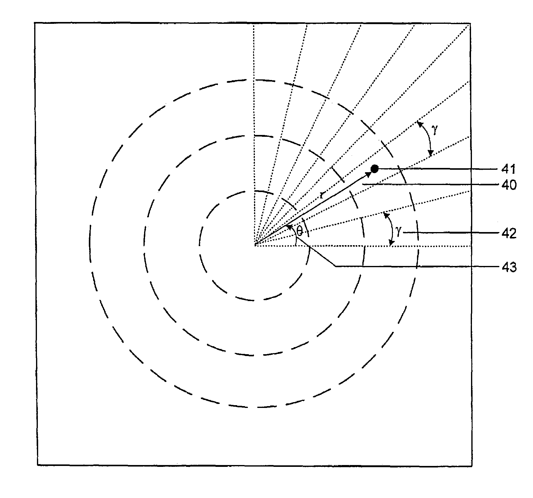
[0011]Fine pointer control may be provided by increasing the number of sectors by increasing either or both of the number of directional zones or the number of velocity zones. If pressure is maintained, and the user moves further away from the centre point, the screen pointer direction movements will get coarser as velocity increases relative to the distance from the centre point. The screen pointer can therefore move a greater distance more quickly with only a relatively small movement along the pressure grid of the controller.
[0012]As the user applies pressure back towards the centre point, the screen pointer″s velocity will slow and accuracy will be restored. For example, if the user wants to quickly move the screen pointer across the screen, the user will venture further away from the centre point in the direction they want to go and a fast, but coarse, screen pointer movement will result. If the user wishes to home the screen pointer in on a specific point on the display, they will stay very close to, or return to, the centre point and slow but accurate movements will result.

Problems solved by technology

However, it does not work well for situations where there is very little room for hand movements, such as on a laptop or handheld computer.
However, all of these devices have the disadvantage of requiring special hardware and requiring a constant transmission of data.
This is fine for systems having a direct connection to their computing devices; however, they are not well suited to low-power, portable wireless systems which do not have the substantial resources required.

Method used


Image

  • Computer pointer control
  • Computer pointer control
  • Computer pointer control

Examples


Embodiment Construction

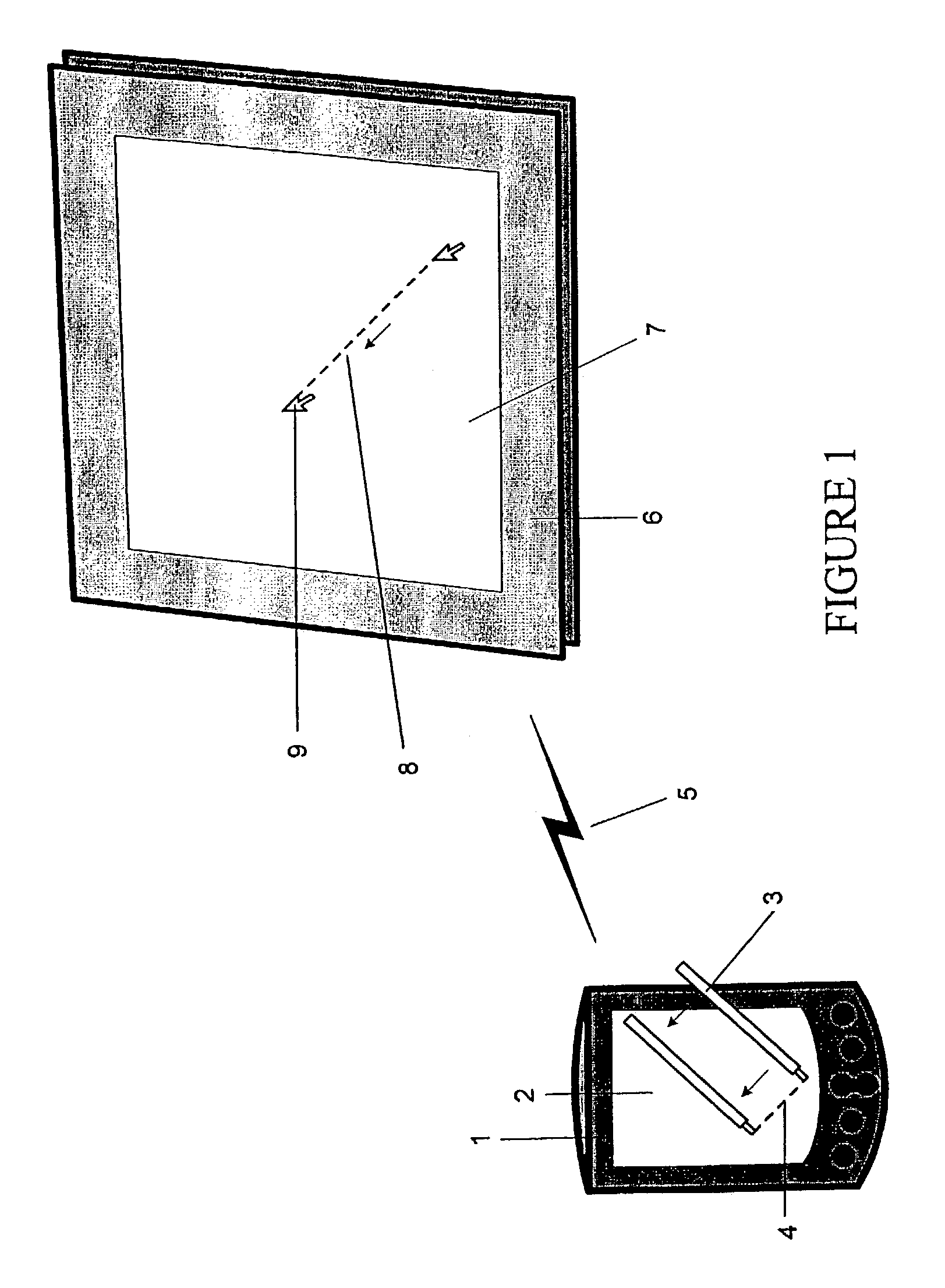
[0044]A computing system which includes the pointer control system of the present invention will include a display device (6) which typically comprises a display screen (7). This display (7) could be an LCD, CRT, projection, or any other device that provides visual feedback and is exemplified by a CRT computer monitor. The other device that is required is a pointer device (1) which may be a handheld computer, cell phone or a personal digital assistant (PDA). This device must have a contact-sensitive sensor area that allows input of pointer commands (2) and could be a touch pad, joystick, or as shown in FIG. 1, a touch screen (2). As used herein, a “contact-sensitive sensor area” means any pre-defined or user defined area where contact and / or movement may be sensed by any means. One embodiment described herein will refer to a pointer area referred to hereafter as a “pad” or “touch pad” having a rectangular shape and area.

[0045]The methods of the present invention may be implemented i...


PUM


Abstract

The present invention relates to a method and system which allows for the transfer of pointer movements and events from small devices with space and data rate constraints to a display device. This will allow a pointer device to be implemented in a small area, but will still enable full pointer movement and event capabilities.

Description

BACKGROUND OF INVENTION[0001]The present invention relates to a method and system for controlling the movement of a computer pointer.[0002]The development of low-power, compact, mobile remote control devices has fostered a need for the development of methods of sending pointer and control information to a display device.[0003]The original pointer controller, now referred to as a “mouse”, was developed in 1964 and has since become one of the primary input devices for a multitude of different computer systems and the dominant input device for personal desktop computing. The mouse, in its current form, works well for situations where there is sufficient room for the movement of the mouse device (approximately one square foot). However, it does not work well for situations where there is very little room for hand movements, such as on a laptop or handheld computer. The prior art describes a variety of different pointer controllers, some of which have been realized into commercial produc...

Claims


Application Information

Patent Timeline
IPC IPC(8): G09G5/08G06F1/16G06F3/033G06F3/048
CPCG06F3/04812G06F1/1626
Inventor FEDORAK, MARK V.CAROLAN, JOHN-MICHAEL B.MILLEY, MILTON E.LOU, EDMOND
Owner META4HAND
Learn More