Modulator-amplifier

a technology of amplifiers and modules, applied in the direction of transducer casings/cabinets/supports, electrical transducers, sonic/ultrasonic/infrasonic transmission, etc., can solve the problems of amplification of audio source signals, consuming energy, and introducing distortion

Inactive Publication Date: 2006-09-19
TURTLE BEACH
View PDF43 Cites 58 Cited by
  • Summary
  • Abstract
  • Description
  • Claims
  • Application Information

AI Technical Summary

Benefits of technology

[0038]23. A modulator-amplifier as set forth in claim 22, wherein the function is chosen so as to minimize switching-induced distortion of audio information in the input signal.
[0071]52. A modulator-amplifier as set forth in claim 51, wherein the function is chosen so as to minimize switching-induced distortion of audio information in the input signal.
[0193]22. A modulator-amplifier as set forth in claim 1, wherein the non-linear relationship is selected to minimize switching-induced distortion of audio information in the output signal.
[0222]42. A modulator-amplifier as set forth in claim 41, wherein the relationship is chosen so as to minimize switching-induced distortion of audio information in the output signal.

Problems solved by technology

The relatively large power requirements of sound reproduction using this technique is an issue recognized across a range of these applications.
Thus changing the excursion direction of the transducer driven element and the coupled medium takes place typically at least this many more times, each change consuming energy.
Furthermore, the processes of modulation of the carrier, and amplification of the audio source signal, can themselves introduce distortion.
For example, audible artifacts of switching in an output stage of a switching amplifier can be problematic.
Further, in switching amplification and modulation at frequencies close to the carrier frequency, e.g. about ten times the frequency or less, very noticeable and distracting artifacts are present using conventional techniques.
These distortions / artifacts can be noticeable, and distracting, when heard by a listener in a parametric array.
They can generally degrade the quality of the audio information heard.
However, due to the necessity for relatively high signal strength, and for increased power in the transducer, these problems remain apparent, and can degrade the listening experience of the hearer in the parametric array.

Method used


Image

  • Modulator-amplifier
  • Modulator-amplifier
  • Modulator-amplifier

Examples


Embodiment Construction

[0348]Reference will now be made to the exemplary embodiments illustrated in the drawings, and specific language will be used herein to describe the same. It will nevertheless be understood that no limitation of the scope of the invention is thereby intended. Alterations and further modifications of the inventive features illustrated herein, and additional applications of the principles of the inventions as illustrated herein, which would occur to one skilled in the relevant art and having possession of this disclosure, are to be considered within the scope of the invention.

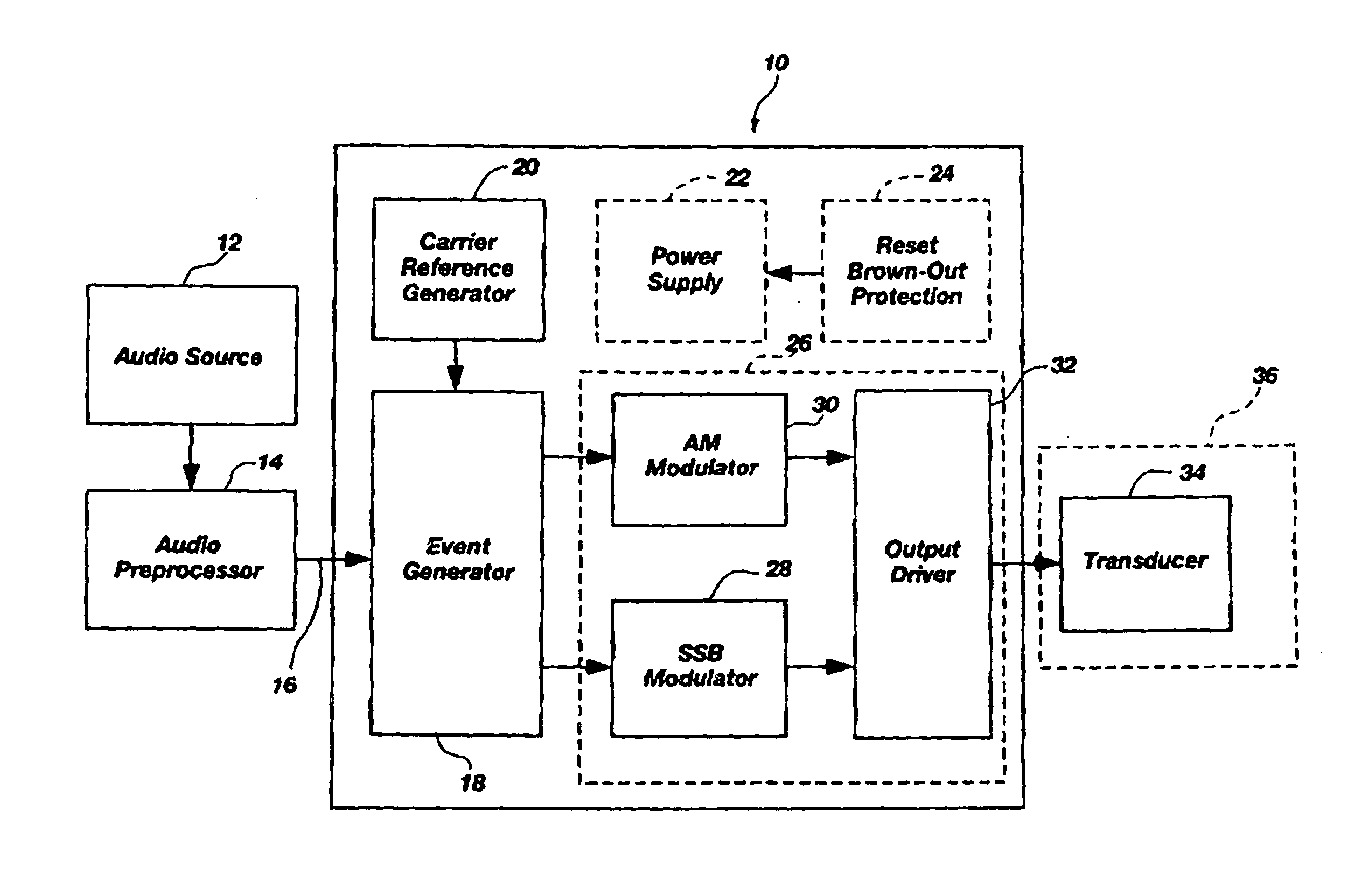
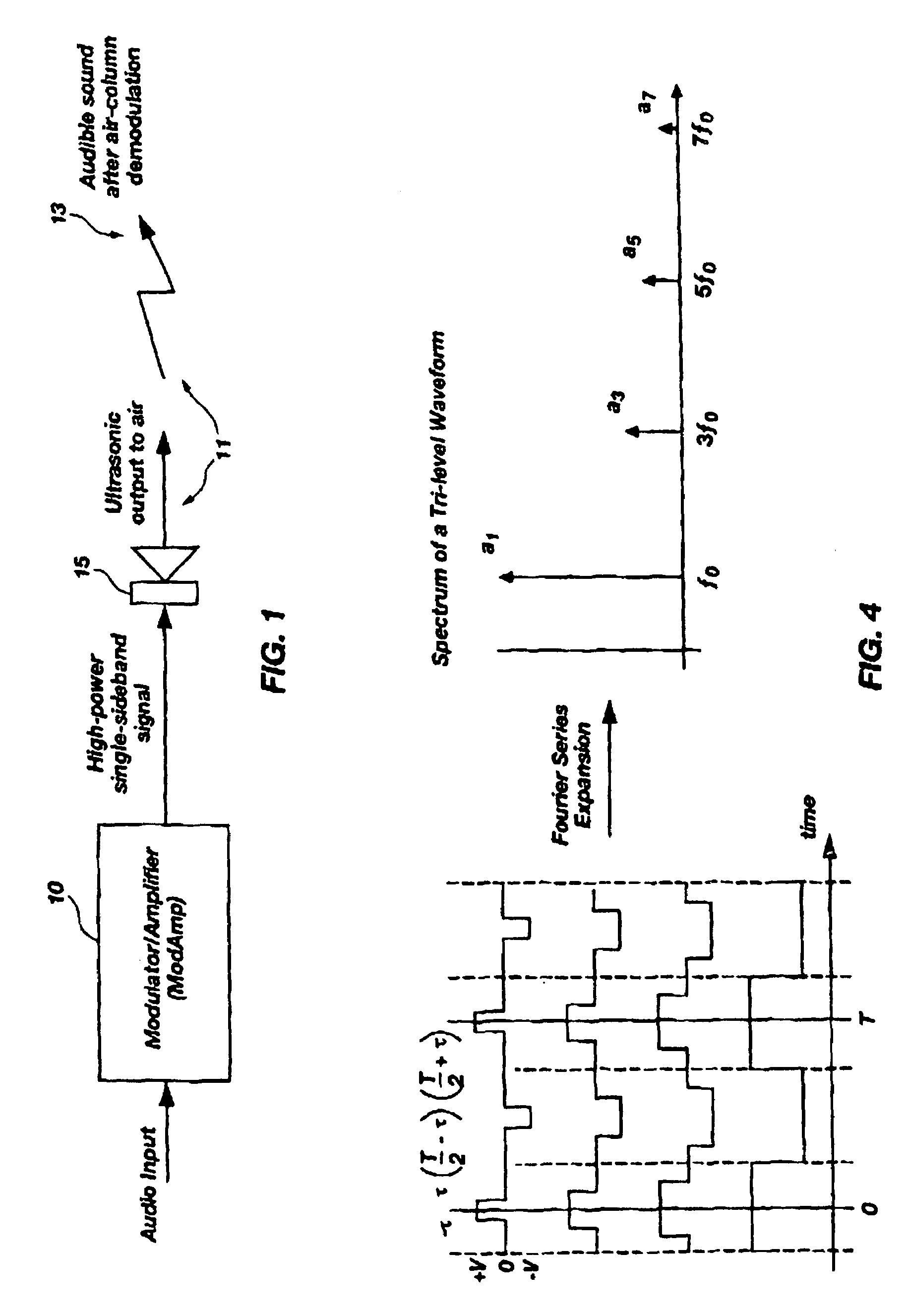
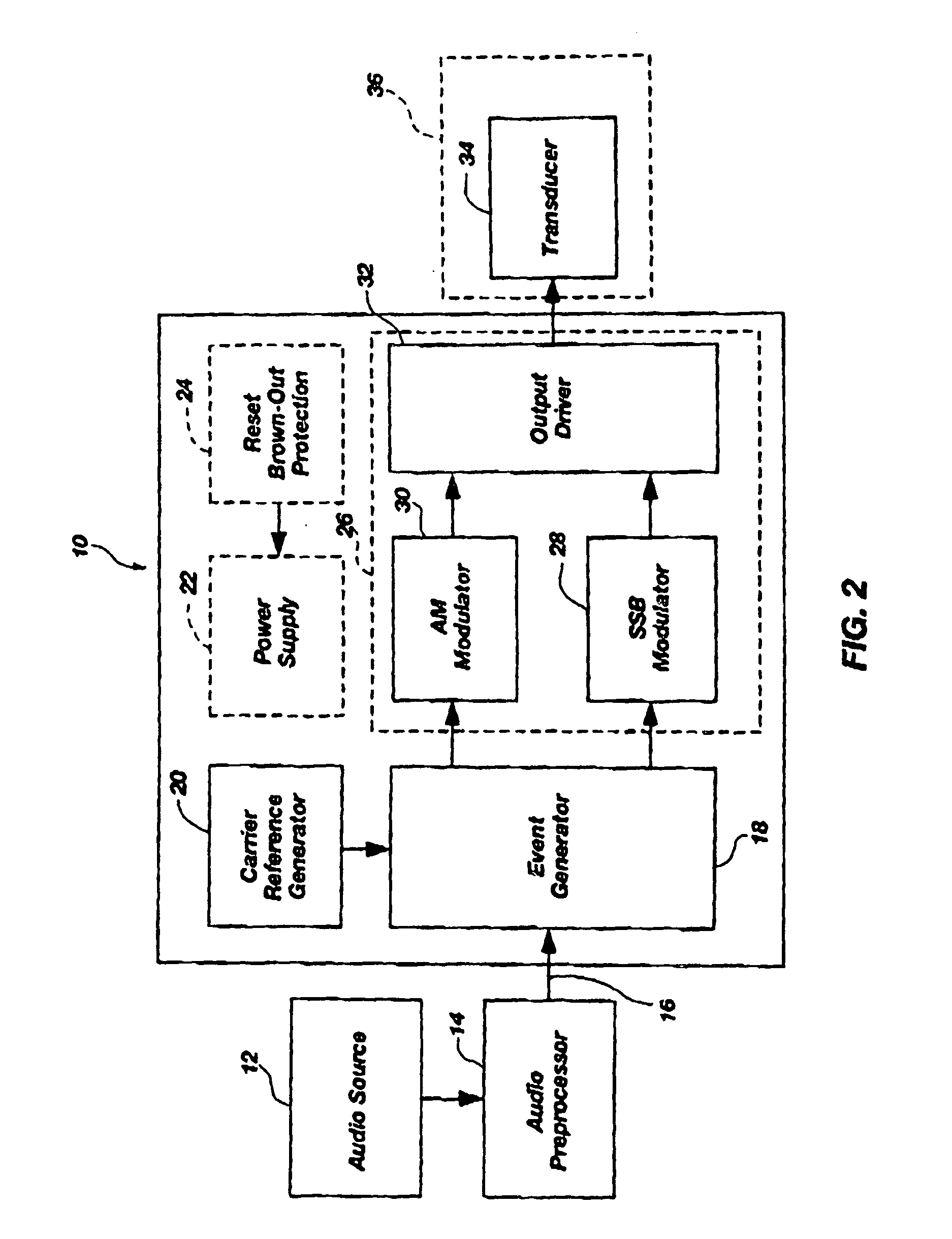
[0349]With reference to FIG. 1, illustrating application of the ModAmp 10 in a parametric array 11. A parametric array system generates audible sound 13 in air using a transducer 15 that emits an inaudible ultrasonic frequency signal at sufficient energy. The non-linear acoustic properties of the air perform demodulation of the ultrasonic signal to generate the audible sound. In a typical parametric: array system...


PUM


Abstract

A modulator-amplifier configured for use in parametric sound reproduction systems, including an input configured for receiving at least one input signal, a reference signal generator configured for generating a reference signal, and a comparator stage coupled to the input and the reference signal generator, the comparator stage configured for detecting relationships between a first signal based on the input signal and the reference signal. A switching power stage coupled to the comparator is configured to receive a second signal derived from a combination of an output from the comparators and the input signal, wherein there is a non-linear relationship between the input signal and the timing of state transitions in the switching power stage for the purpose of generating an output that has been shifted in frequency relative to a frequency of the input signal, and which includes at least one sideband.

Description

[0001]This application claims priority of U.S. Provisional Application Ser. No. 60 / 350,414 filed Jan. 18, 2002, which is hereby incorporated herein by reference for the relevant teachings consistent herewith.BACKGROUND OF THE INVENTION[0002]1. Field of the Invention[0003]The present invention relates generally to modulators and amplifiers used in communication and reproduction of audio signals. More particularly, the present invention relates to amplification and modulation equipment where a carrier is modulated in at least one sideband in parametric sound reproduction.[0004]2. Related Art[0005]Modulation of a carrier signal to incorporate audio signal information is well known. Single side band (SSB) and double side band (DSB or AM) modulation including “upper” and “lower” sidebands have been used in radio frequency (RF) communication equipment for many decades to transmit and reproduce audio information. More recently, in the field of parametric audio reproduction, modulation of a...

Claims


Application Information

Patent Timeline
Patent Type & Authority Patents(United States)
IPC IPC(8): H03F3/38H04R3/00H03F3/217H03F3/66
CPCH03F3/2171H04B11/00H03F3/66H03F2200/331H03F3/38
Inventor SPENCER, MICHAEL E.
Owner TURTLE BEACH
Why Eureka
Try Eureka