
Turbocharger with hydrodynamic foil bearings

a technology of hydrodynamic foil bearings and turbochargers, which is applied in the direction of positive displacement liquid engines, piston pumps, bearing cooling, etc., can solve the problems of reducing the oil pressure of the turbocharger, affecting the performance of the turbocharger, and increasing the undesirable emissions of the engin

Active Publication Date: 2006-09-19
GARRETT TRANSPORATION I INC
View PDF32 Cites 68 Cited by
  • Summary
  • Abstract
  • Description
  • Claims
  • Application Information

AI Technical Summary

Benefits of technology

This solution enhances the durability and orientation flexibility of turbochargers, reduces emissions, and extends the lifespan of foil bearings by effectively managing temperature and contamination, while maintaining high stiffness and stability at high speeds.

Problems solved by technology

Oil-lubricated turbochargers are prone to oil seal failures.
If the oil seal on the turbine side of the turbocharger fails and allows oil to leak into the turbine, the oil ends up being discharged into the engine exhaust system, which can increase undesirable emissions from the engine.
On the other hand, operation under very cold conditions can lead to a delay of the oil pressure reaching the turbocharger and can also result in turbo bearing durability problems.
Additionally, oil-lubricated turbochargers are restricted to being used in a particular horizontal orientation, since they depend on gravity for draining the oil from the bearings.
As a result, the engine or vehicle designer does not have much freedom with respect to placement of the turbocharger.
However, prior to the present invention, it is believed no production turbochargers incorporating foil bearings have been developed, at least in part because difficulties have been encountered in adequately cooling the foil bearings.
Without adequate cooling, foil bearings tend to have short useful lives.
Thus, while the benefits of incorporating foil air bearings into a turbocharger are well understood, significant technical challenges have to be overcome to develop a practical design.

Method used


Image

  • Turbocharger with hydrodynamic foil bearings
  • Turbocharger with hydrodynamic foil bearings
  • Turbocharger with hydrodynamic foil bearings

Examples


Embodiment Construction

[0019]The present inventions now will be described more fully hereinafter with reference to the accompanying drawings, in which some, but not all embodiments of the invention are shown. Indeed, these inventions may be embodied in many different forms and should not be construed as limited to the embodiments set forth herein; rather, these embodiments are provided so that this disclosure will satisfy applicable legal requirements. Like numbers refer to like elements throughout.

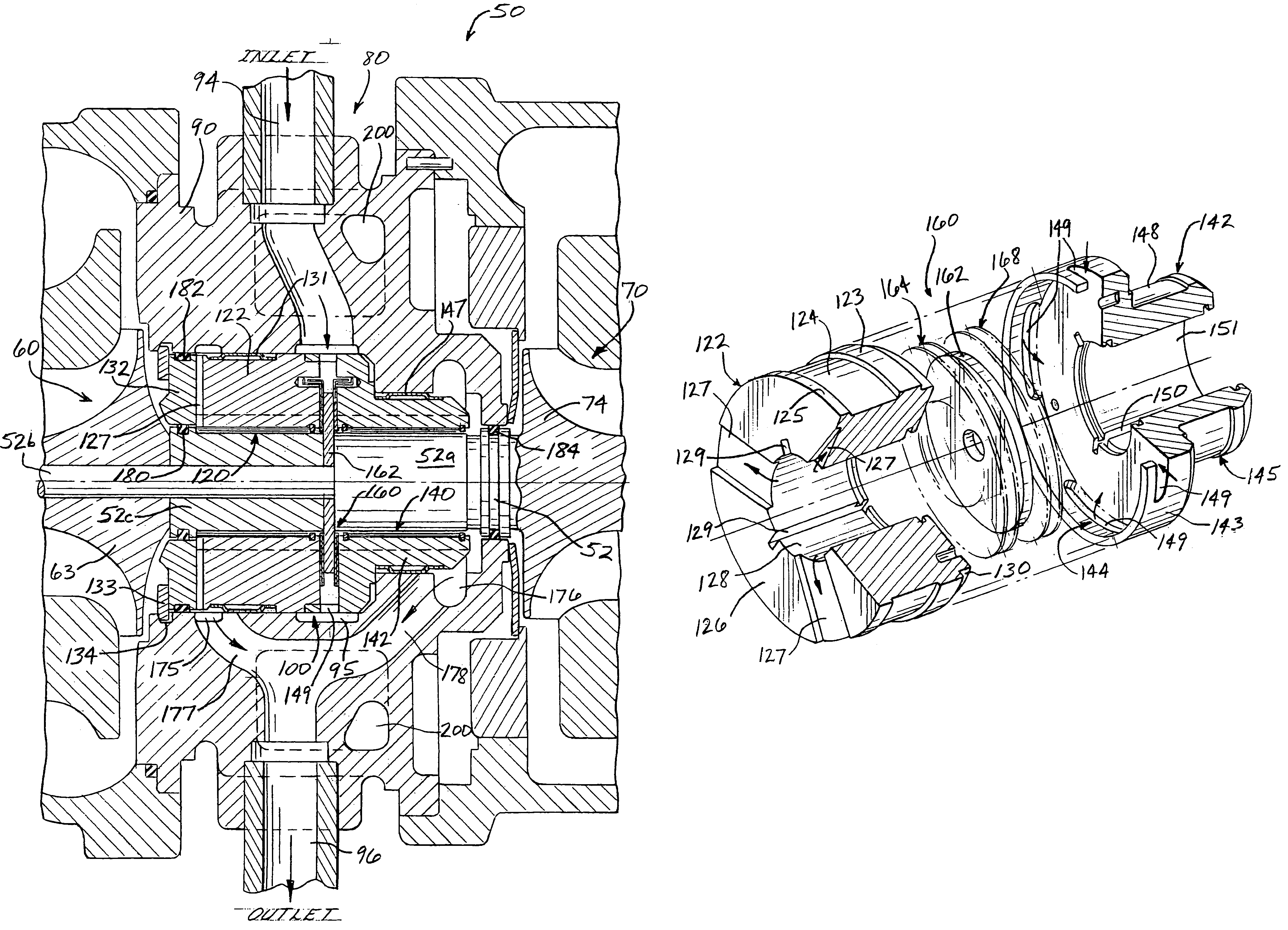
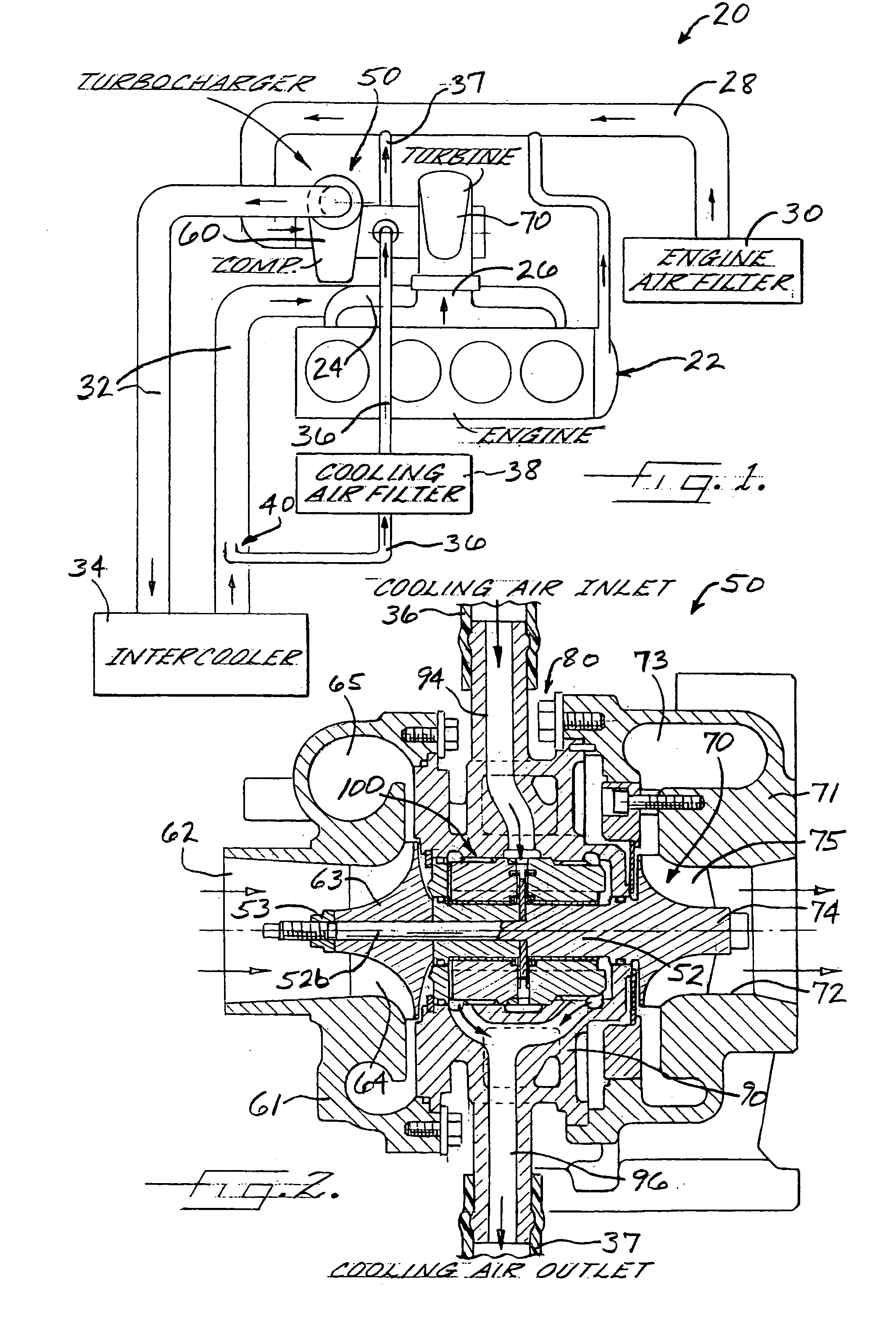
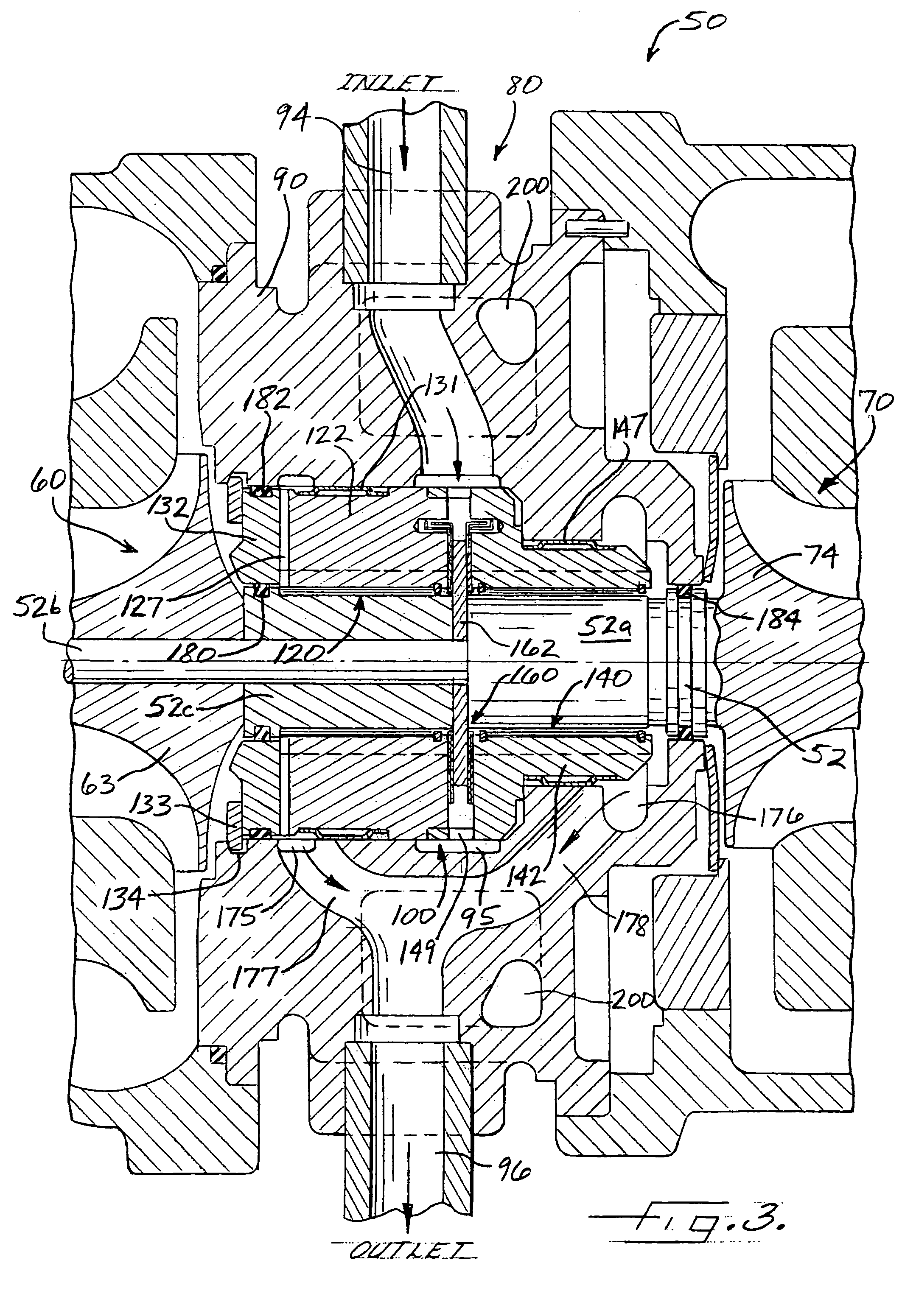
[0020]FIG. 1 schematically depicts an engine system 20 in accordance with an embodiment of the present invention, employing an “oil-less” turbocharger having foil bearings. The system 20 includes an engine 22, shown as a reciprocating internal-combustion engine. The engine can be of various types, including diesel engines or gasoline engines, having various numbers and arrangements of cylinders. The engine includes an air intake 24 through which air is supplied to the engine for mixing with fuel to be burned in...


PUM


Abstract

A turbocharger includes a foil bearing assembly mounted in a center housing between a compressor and a turbine of the turbocharger. The bearing assembly forms a unit installable into the center housing from one end thereof, and the center housing is a one-piece construction. The bearing assembly includes a foil thrust bearing assembly disposed between two foil journal bearings. The journals foils are mounted in annular bearing carriers fixedly mounted in the center housing. A radially inner portion of a thrust disk of the thrust bearing assembly is captured between a shaft and a shaft sleeve of the turbocharger. The center housing defines cooling air passages for supplying cooling air to the foil bearings, and optionally includes a water jacket for circulating engine coolant through the center housing.

Description

BACKGROUND OF THE INVENTION[0001]The invention relates to turbochargers used for boosting the performance of engines such as diesel and gasoline automotive engines and the like.[0002]Turbochargers for diesel and gasoline automotive engines have conventionally employed oil-lubricated bearings. The turbocharger is connected to the engine oil system and engine oil is supplied into the bearing housing of the turbocharger to lubricate the bearings, and the oil is then discharged from the bearing housing and returned to the engine oil system.[0003]Oil-lubricated turbochargers are prone to oil seal failures. If the oil seal on the turbine side of the turbocharger fails and allows oil to leak into the turbine, the oil ends up being discharged into the engine exhaust system, which can increase undesirable emissions from the engine.[0004]The durability of an oil-lubricated turbocharger is highly dependent on the engine lubrication system. The now common use of low-viscosity oils and high engi...

Claims


Application Information

Patent Timeline
Patent Type & Authority Patents(United States)
IPC IPC(8): F02B17/00F02B33/44F16C32/06B61F17/00F02B35/00F01D25/16F02C6/12F16C17/12
CPCF16C17/024F16C17/042F16C2360/24F16C37/002
Inventor LARUE, GERALD DUANEKANG, SUN GOOWICK, WERNER
Owner GARRETT TRANSPORATION I INC
Learn More