
Mask with gusset

a mask and gusset technology, applied in the field of masks with gussets, can solve the problems of reducing the desired air pressure in the mask, increasing noise, reducing the effectiveness of therapy, and compliance with therapy, and achieves the effects of enhancing mechanical flexibility, ensuring safety, and ensuring patient comfort and complian

Inactive Publication Date: 2006-09-19
RESMED LTD
View PDF58 Cites 149 Cited by
  • Summary
  • Abstract
  • Description
  • Claims
  • Application Information

AI Technical Summary

Benefits of technology

The invention is a mask system for patients with sleep apnea that uses a flexible cushion to transfer forces to the patient's face. The mask system includes a shell and a cushion that can move relative to each other. The force exerted on the cushion is a function of mask pressure or the displacement of the shell relative to the face. The mask system can provide a secure seal even when the patient moves during sleep. The gusset section between the shell and cushion increases the flexibility of the mask without requiring a stronger headgear tension, providing greater patient comfort and compliance with the prescribed respiration therapy regime. The mask system also includes a baffle element to reduce carbon dioxide buildup and short-circuiting of the intake gas. Overall, the invention improves the effectiveness and comfort of mask therapy for patients with sleep apnea.

Problems solved by technology

Leaks between the mask and the patient's face can reduce the desired air pressure in the mask and create increased noise.
Both can reduce the effectiveness of, and compliance with, the therapy.
In the latter, the increased noise can disrupt the sleep cycle of both the patient and the patient's bed partner.
Leaks are especially prone to occur as the patient moves during the night.
Drag and movement of the air delivery tube or the mask system as the patient turns or moves can alter the positioning and alignment of the mask with respect to the patient's face, which movement can be translated or transferred to the cushion seal, creating leaks.
Thus, while the mask may initially be leak free when attached to the patient, leaks are prone to develop later in the night as the patient moves in bed, awakening the patient.
Further, since leaks are disruptive of both the sleeping cycle and the prescribed therapy regimen, patients will often tighten the straps even more than is necessary to prevent leaks at the maximum encountered air pressure.
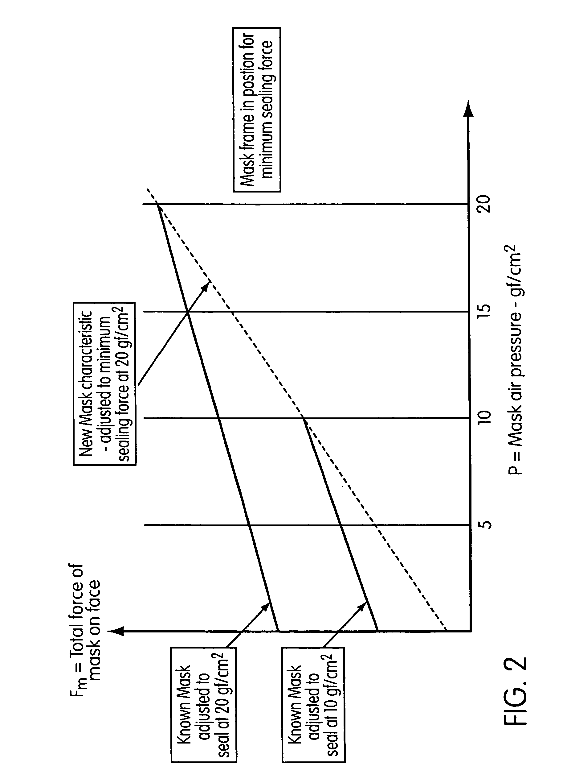
In known masks, this higher than necessary strap pressure directly results in a higher than necessary force of the mask cushion on the patient's face, particularly as the pressure goes below the maximum mask air pressure.
The force of the mask cushion on the patient's face is difficult to distribute completely evenly around the cushion in known masks, especially at higher forces, and results in localized high pressure spots around the mask cushion.
This higher force on the face, and especially the localized high pressure spots, are uncomfortable to the patient and can disrupt the sleep cycle.
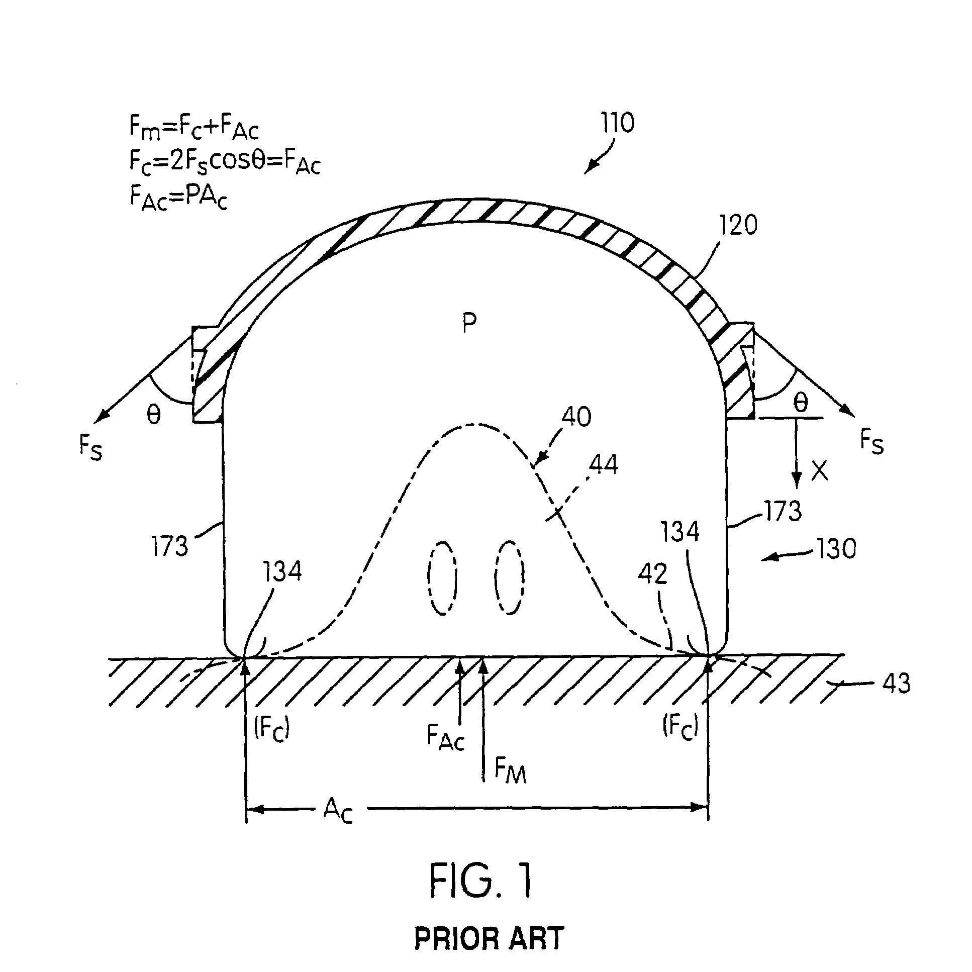
The mask shell may be able to move beyond Xp but the cushion tends to become rigid or nearly so at about Xp, thereby limiting further travel.
Although the bellows provides limited mechanical flexibility, no significant pressure advantages or significant mechanical flexibility can be achieved.
This mask does not overcome the sealing problems incurred by movement of the mask with respect to the patient's face without utilizing an increased head strap pressure across the mask air pressure operating range.

Method used


Image

  • Mask with gusset
  • Mask with gusset
  • Mask with gusset

Examples


Embodiment Construction

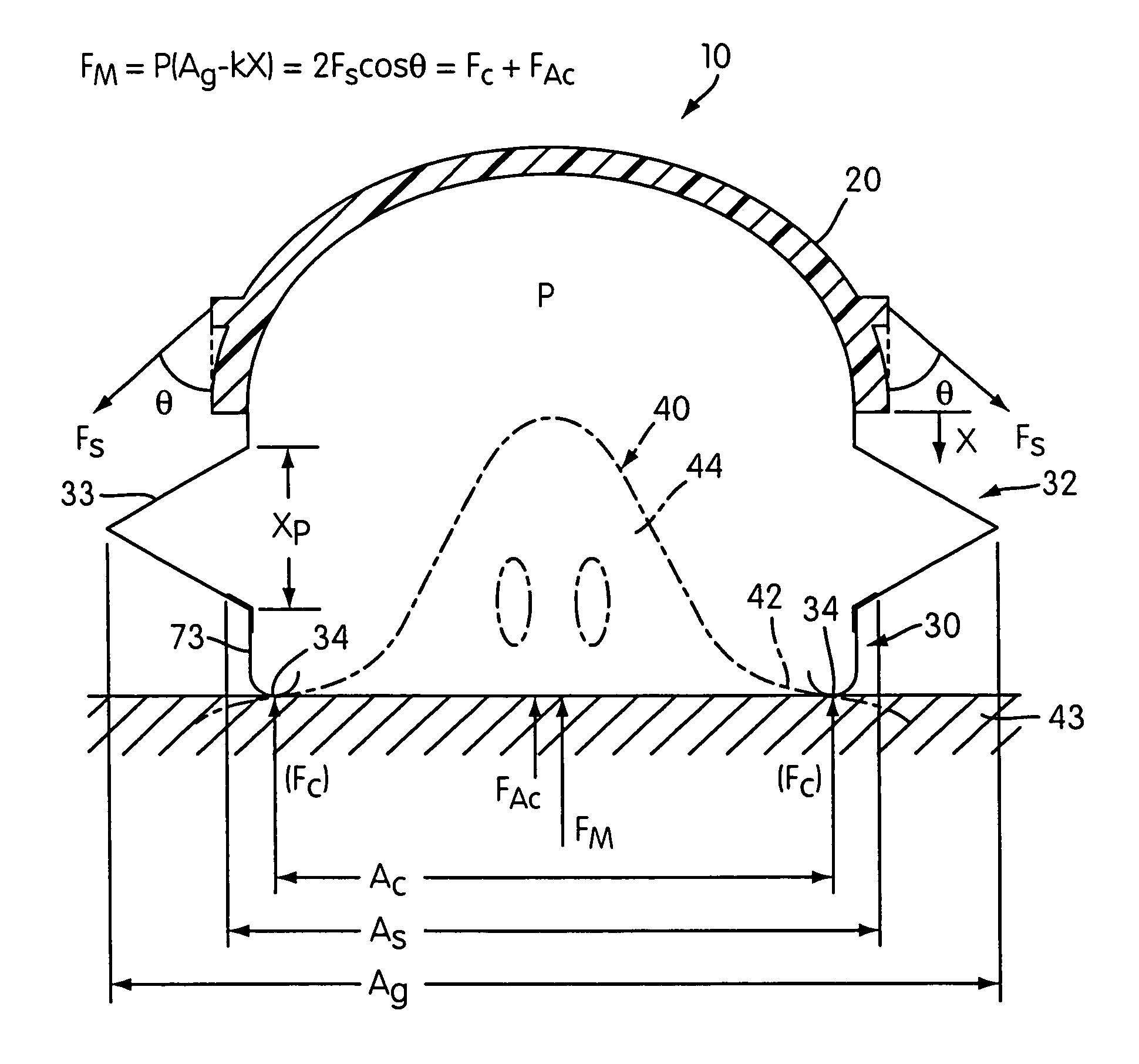
[0044]A first embodiment of the respiratory mask 10 of the present invention is shown in FIGS. 4–9. The mask 10 includes a generally rigid shell 20 having an air tube 22 for connecting to a pressurized air supply 23. A gusset portion 32 is attached to the shell 20 in a known manner such as gluing or mechanical fastening. The gusset portion 32 acts as a suspension mechanism for a cushion 30 and includes a flexible gusset sidewall 33. A partial sectional view of the gusset portion 32 is shown in FIG. 6. In this embodiment, the gusset sidewall 33 has a generally uniform thickness and the gusset portion 32 has a generally triangular cross-section when not exposed to mask pressure. However, in this embodiment, the flexible sidewall 33 will balloon out when the mask 10 is pressurized to take on the more rounded cross-section shown in FIG. 7. The FIG. 8 end view of the gusset portion 32 shows that the gusset has a generally triangular outline to conform with the shape of the cushion 30 and...


PUM


Abstract

A mask system for delivering air to a user includes a suspension mechanism to allow relative movement between a face-contacting cushion and a mask shell. The suspension mechanism also provides a predetermined force to the cushion that is a fiction of mask pressure, displacement of the cushion or both.

Description

CROSS REFERENCE TO RELATED APPLICATION[0001]This application is a divisional of application Ser. No. 10 / 322,578, filed Dec. 19, 2002, now U.S. Pat. No. 6,772,760, which is a continuation of U.S. application Ser. No. 09 / 885,445, filed Jun. 21, 2001, now U.S. Pat. No. 6,986,352, which in turn claims the benefit of U.S. Provisional Application No. 60 / 213,251, filed Jun. 22, 2000, U.S. Provisional Application No. 60 / 219,618, filed Jul. 21, 2000, and U.S. Provisional Application No. 60 / 293,992, filed May 30, 2001, the entire contents of which are incorporated herein by reference.[0002]This invention relates generally to masks for use in respiratory therapy. One use is in CPAP treatment of Obstructive Sleep Apnea. However, the mask arrangements presented herein are useful in other types of respiratory therapy. In the quest for an improved mask arrangement for respiratory therapy, there are various design objectives—effectiveness of seal between the mask and the patient's face, good compli...

Claims


Application Information

Patent Timeline
Patent Type & Authority Patents(United States)
IPC IPC(8): A62B18/02A61M16/06
CPCA61M16/06A61M16/0633A61M16/0616A61M16/0622A61M16/0611A61M2206/14A61M16/0057A61M16/0683A61M2205/3331
Inventor FRATER, ROBERT H.DREW, JOANNEGUNARATNAM, MICHAEL K.
Owner RESMED LTD
Learn More