Eureka AIR delivers breakthrough ideas for toughest innovation challenges, trusted by R&D personnel around the world.

Deployable medical lead fixation system and method

a technology of lead fixation and medical devices, which is applied in the field of implantable medical devices, can solve the problems of inability to achieve fixation, inconvenient method for maintaining the position of a lead within a vessel, and insufficient expansion of tines to the vessel walls,

Inactive Publication Date: 2006-09-12
MEDTRONIC INC
View PDF16 Cites 160 Cited by
  • Summary
  • Abstract
  • Description
  • Claims
  • Application Information

AI Technical Summary

Benefits of technology

[0009]The current invention provides a lead assembly that includes a lead body, and a spring member positioned adjacent to the lead body. The spring member may be deployed a selectable amount to maintain the lead in a fixed location within a patient's body. The spring member may be an expandable coil, a mesh structure that is similar to a stent, or any other similar device that may be positioned in a low-profile state during a l

Problems solved by technology

One problem with positioning leads within the body relates to maintaining the leads at a desired location.
While the foregoing fixation mechanisms are adequate for affixing a lead within a heart chamber, these methods are not particularly suited for maintaining the position of a lead within a vessel.
Although tines may be used to lodge a lead within a vessel, the tines may undesirably block a substantial portion of the blood flow through the vessel.
In other cases wherein leads are positioned within large vessels such as the coronary sinus, the tines are often not large enough to extend to the vessel walls to accomplish fixation.
Similar problems exist with active fixation mechanisms.
This makes fixation using the helix difficult.
This method of fixation occludes the vessel, however, and is therefore not desirable for use in chronic implant situations.
Additionally, this type of mechanism makes chronic lead removal difficult, if not impossible, since the stent will become attached to surrounding tissue over time.
Finally, the disclosed stent may not be deployed a selectable amount to accommodate vessels of varying sizes.

Method used


Image

  • Deployable medical lead fixation system and method
  • Deployable medical lead fixation system and method
  • Deployable medical lead fixation system and method

Examples


Embodiment Construction

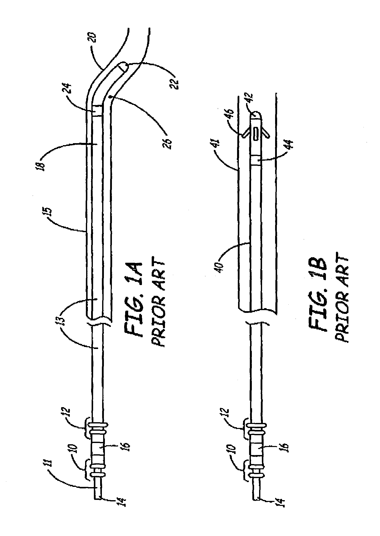
[0037]FIG. 1A is a side view of a prior art medical electrical lead. The lead has a proximal end 11 including pairs of sealing rings 10 and 12, a pin connector 14, and a ring connector 16. The lead further includes a lead body 13 that may be formed of a biocompatible material such as polyurethane or silicone. A distal end 18 of the lead, which is shown implanted within a vein 20, includes a tip electrode 22 and a ring electrode 24. A curve 26 is provided to wedge distal end within vein 20, and to further urge tip electrode 22 against tissue. If a vein 15 is large, however, as is the case in FIG. 1A, the curve is not large enough to provide adequate fixation of the lead within vein 15.

[0038]FIG. 1B is a side view of another prior art medical electrical lead showing a distal end 40 of the lead implanted within a vein 41. Distal end 40 includes a tip electrode 42, optional ring electrode 44, and traditional fixation tines 46. In a manner similar to that shown in FIG. 1A, fixation tines...


PUM


Abstract

An improved medical lead assembly and method of use is provided. The lead assembly includes a lead body, and a spring member positioned adjacent to the lead body. The spring member may be deployed a selectable amount to maintain the lead body in a fixed location within a patient's body. The spring member may be an expandable coil, a mesh structure that is similar to a stent, or any other similar device that may be positioned in a low-profile state during a lead implant procedure. After the lead is positioned at a target destination, the spring member may be deployed an amount that is selected based on the characteristics of the surrounding tissue, including vessel size. According to one aspect of the invention, the lead assembly may provide means for facilitating chronic lead extraction.

Description

FIELD OF THE INVENTION[0001]The present invention relates generally to implanting medical leads within a body and, more particularly, to a system and method for maintaining a medical lead at a site of implant using a deployable fixation mechanism.BACKGROUND OF THE INVENTION[0002]It is common practice to treat many types of ailments by implanting medical leads within a body. For example, if a person's heart does not beat properly, medical electrical leads may be positioned within the heart or surrounding vessels to deliver electrical stimulation to the heart.[0003]One problem with positioning leads within the body relates to maintaining the leads at a desired location. When a lead is used to deliver an electrical signal to the heart, for example, it is important to maintain the device at a desired position so that the signal will cause desired electrical depolarization of the tissue. If the device shifts position, this desired depolarization may not occur.[0004]The foregoing problem ...

Claims


Application Information

Patent Timeline
IPC IPC(8): A61N1/05
CPCA61N1/056A61N2001/058A61N1/057
Inventor BJORKLUND, VICKI L.SOMMER, JOHN LHINE, DOUGLAS S.LOVE, CHARLES J.HESS, DOUGLAS N.LOKHOFF, NICOLAAS M.
Owner MEDTRONIC INC
Why Eureka
Eureka Blog
Learn More