
Electric current detection apparatus

a detection apparatus and current technology, applied in the direction of instruments, base element modifications, transportation and packaging, etc., can solve the problems of inefficient measurement, difficult to find space for mounting the electric current detection apparatus, and respect for detection accuracy, so as to achieve accurate determination

Inactive Publication Date: 2006-09-12
DENSO CORP
View PDF17 Cites 26 Cited by
  • Summary
  • Abstract
  • Description
  • Claims
  • Application Information

AI Technical Summary

Benefits of technology

[0013]It is an object of the present invention to overcome the above problems of the prior art, by providing an electric current detection apparatus having a single electric current detector that can accurately detect respective levels of current that flow in two different systems during respectively different conduction occasions, with the respective current flows differing greatly in dynamic range. It is a further objective to provide such an electric current detection apparatus which has a simple configuration and which can thereby be manufactured at low cost.
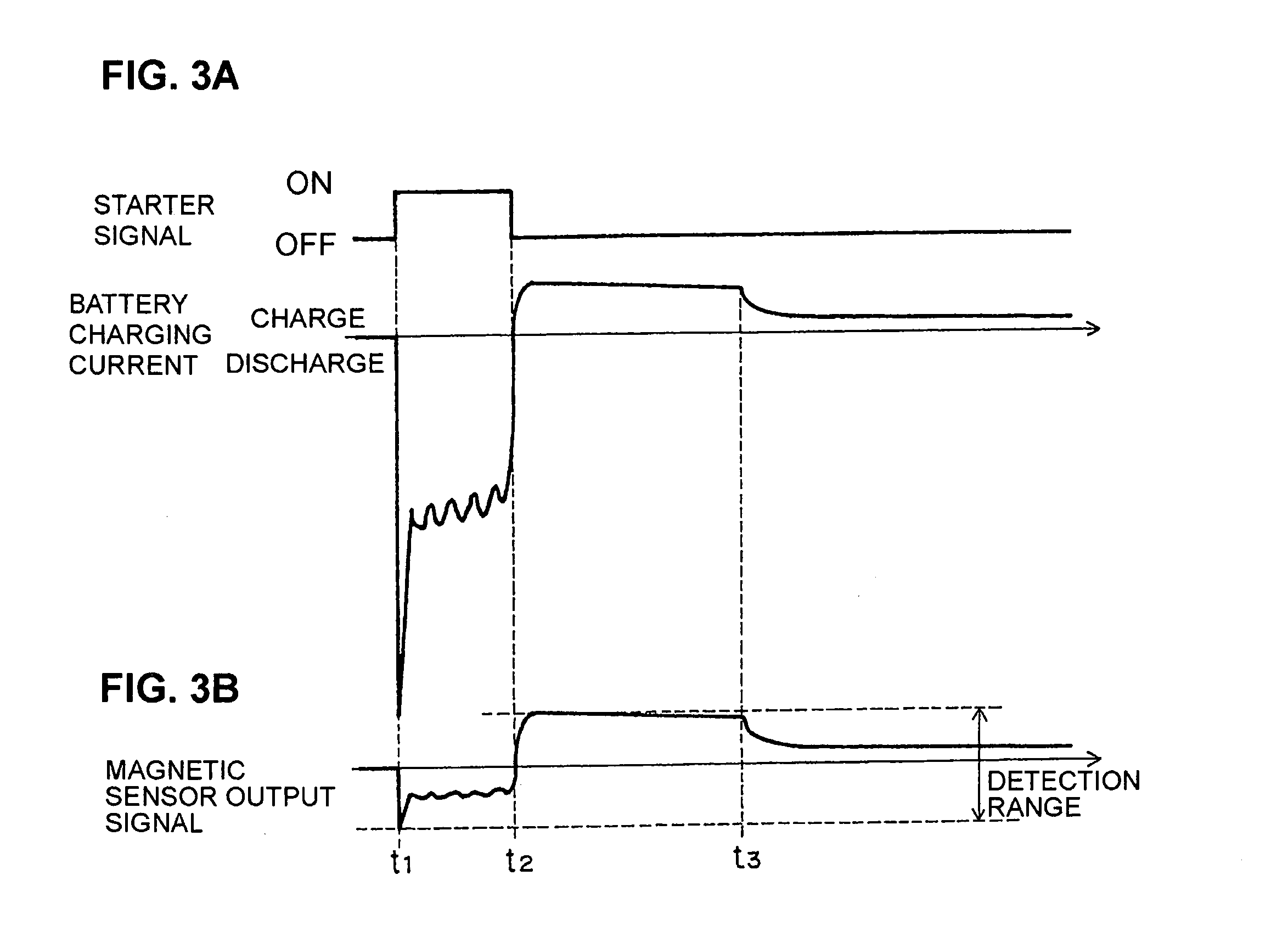
[0016]In that way, levels of current flow along the first current path and of current flow along the second current path can each be accurately detected using the same magnetic sensor, even if the respective current levels differ substantially.
[0017]Such an electric current detection apparatus is suitable for a vehicle application, with respective first ends of the first, second and third conductors being electrically connected to a positive terminal of the vehicle battery, respective second ends of the first and third conductors electrically connected through the first current path to a first electrical load that is constituted by the starter motor of the vehicle, and a second end of the second conductor electrically connected through the second current path to a second electrical load that is constituted by other equipment of the vehicle. In that way, a single magnetic sensor can be used to detect a high level of current supplied from the battery to the starter motor during respective conduction occasions (i.e., each period during which battery charging is performed) and low levels of current that are supplied from the battery to the second load (or received, as a charging current by the battery), during different conduction occasions from those of the first load (i.e., occurring after engine starting has been completed).
[0024]In that way even if the magnetic sensor has a temperature dependency, accurate detection of values of magnetic flux and hence accurate detection of current values can be achieved.
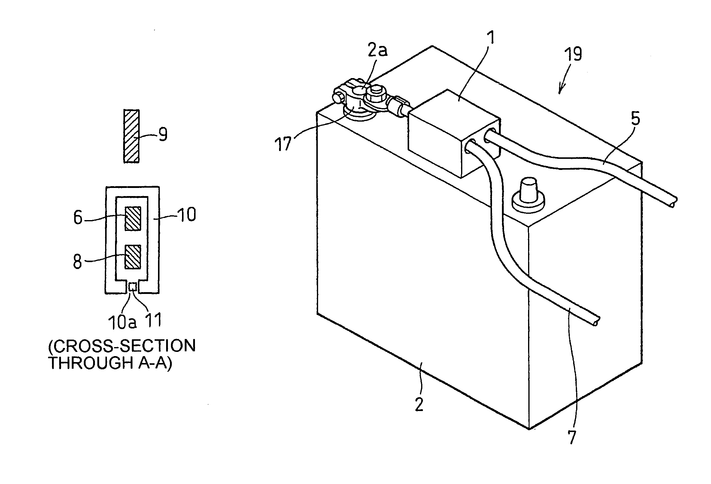
[0025]Furthermore, the invention provides a battery module suitable for use in a vehicle, consisting of an electric current detection apparatus according to the present invention mounted on a vehicle battery. This has the advantage of a compact configuration, with only a minimum length of connecting lead being required between the electric current detection apparatus and the positive terminal of the battery.
[0030]In that way, the SOH of the battery can be accurately determined each time that engine starting occurs, and can be continuously monitored after engine starting has been completed.

Problems solved by technology

However if the detection range is made so large, then the detection resolution will become correspondingly lower, so that problems arise with respect to accuracy of detection when measuring the levels of battery current that flow after engine starting has been completed.
However if an electric current detection apparatus utilizing two current detectors having respectively different detection ranges is used, then the overall size of the apparatus will become large, so that it is difficult to find space for mounting the electric current detection apparatus in the vehicle, and in addition this is not an efficient measure, from the aspect of manufacturing costs.
Hence, the structure becomes complex, so that the manufacturing cost is high.
Furthermore, due to the inductance of the feedback winding, the problem arises that the switching response when changing the detection range is poor.

Method used


Image

  • Electric current detection apparatus
  • Electric current detection apparatus
  • Electric current detection apparatus

Examples


first embodiment

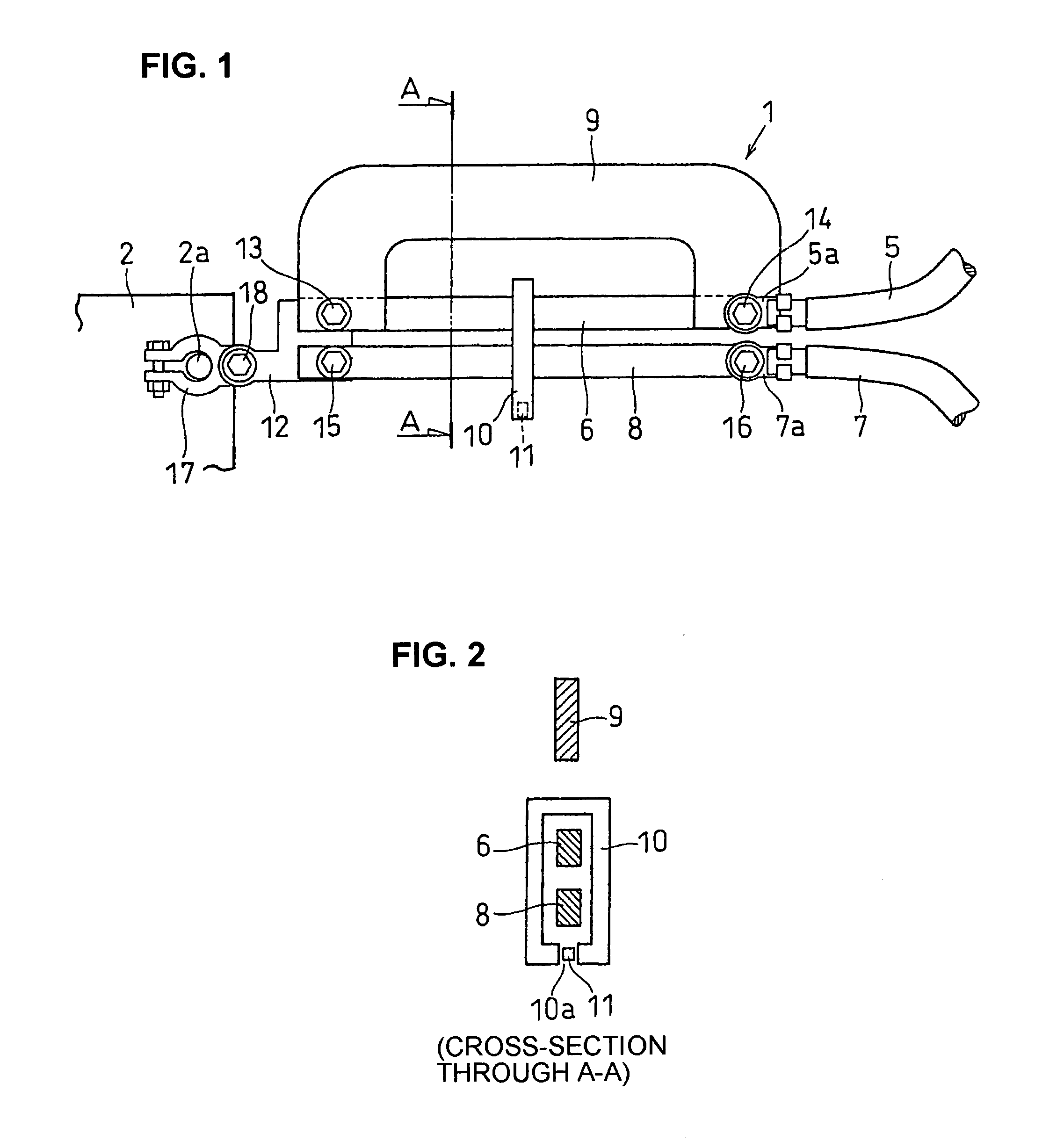
[0041]FIG. 1 is a plan view of an electric current detection apparatus 1 according to a first embodiment. This is applicable for example to a battery status monitoring system such as that shown in FIG. 7 (described in more detail hereinafter), for detecting a starting current that flows from a battery 2 to a starter motor 3 (also shown in FIG. 7) when starting of a vehicle engine is performed, and for monitoring a charging current that flows from a generator 4 of the vehicle into the battery 2, and moreover for detecting a discharge current that flows from the battery 2 to other electrical equipment of the vehicle (such as headlamps, air conditioner, navigation apparatus, etc.).

[0042]FIG. 2 is a cross-sectional view taken through a plane A—A indicated in FIG. 1. As shown in FIG. 1, the electric current detection apparatus 1 is made up of a 1st conductor 6 that is connected to a 1st supply lead 5 of a first current path, a 2nd conductor 8 that is connected to a 2nd supply lead 7 of a...

second embodiment

[0061]FIG. 4 is a plan view of an electric current detection apparatus, designated by numeral 100, according to a second embodiment. In FIG. 4, components corresponding to components in the electric current detection apparatus 1 of FIG. 1 are indicated by reference numerals respectively corresponding to those in FIG. 1, and detailed description of these will be omitted. With the first embodiment described above, the 1st conductor 6 and the 3rd conductor 9 are connected mutually in parallel and are connected in common to the 1st supply lead 5. Hence at the time of engine starting, the starting current branches through the 1st conductor 6 and the 3rd conductor 9, thereby reducing the proportion of the starting current that flows through the first conductor 6. However with the second embodiment, there is no reduction of the proportion of the charging current that flows through the 1st conductor 6 during engine starting. Instead, the magnetic flux that is generated by the flow of normal...

third embodiment

[0072]FIG. 6 is an oblique view of a battery module 19 according to a third embodiment of the invention. With this embodiment the electric current detection apparatus 1 of the first embodiment (or the electric current detection apparatus 100 of the second embodiment) attached within a case that is formed of a material such as synthetic resin, cast aluminum, etc., is mounted on a battery 2 as shown, to thereby constitute a battery module 19. Since the electric current detection apparatus 1 is directly mounted on the battery 2, the connecting lead between the electric current detection apparatus 1 and the terminal 17 the battery 2 can be very short, and space saving can be achieved.


PUM


Abstract

An electric current detection apparatus has a single magnetic sensor for detecting a first current which flows from a battery and also a second current which flows into or from the battery during different occasions from the first current and is substantially smaller than the first current. The magnetic sensor has a magnetic core surrounding first and second conductors, with the second conductor carrying the second current and with the first conductor being shunted by a third conductor such as to conduct a predetermined proportion of the first current.

Description

BACKGROUND OF INVENTION[0001]1. Field of Application[0002]The present invention relates to an electric current detection apparatus for detecting values of electric current flow in each of two systems which always have respectively different conduction occasions, where the term “conduction occasion” is used herein to signify a time during which current flow occurs through a specific electrical system or conductor.[0003]In particular, the invention relates to such an electric current detection apparatus that is applicable to two systems having a large difference between the respective dynamic ranges of currents which flow in the two systems. The invention further relates to an electric current detection system, a battery module which combines a current detection function with a storage battery, and a battery status monitoring method, each of which utilize such an electric current detection apparatus.[0004]2. Prior Art Technology[0005]In recent years, with increasing amounts of electri...

Claims


Application Information

Patent Timeline
Patent Type & Authority Patents(United States)
IPC IPC(8): G01R33/07G01R15/18G01R15/20G01R15/14G01R19/00G01R31/36
CPCG01R15/181G01R31/3606B60L2240/545B60L2240/547B60L2240/549G01R31/3696G01R31/3648G01R31/3662G01R31/3675G01R1/203G01R15/183G01R15/20G01R31/364G01R31/374G01R31/382G01R31/389
Inventor TANIGUCHI, MAKOTO
Owner DENSO CORP
Learn More