
Stereo/two-tone demodulator

Inactive Publication Date: 2006-09-05
KONINKLIJKE PHILIPS ELECTRONICS NV
View PDF7 Cites 0 Cited by
  • Summary
  • Abstract
  • Description
  • Claims
  • Application Information

AI Technical Summary

Benefits of technology

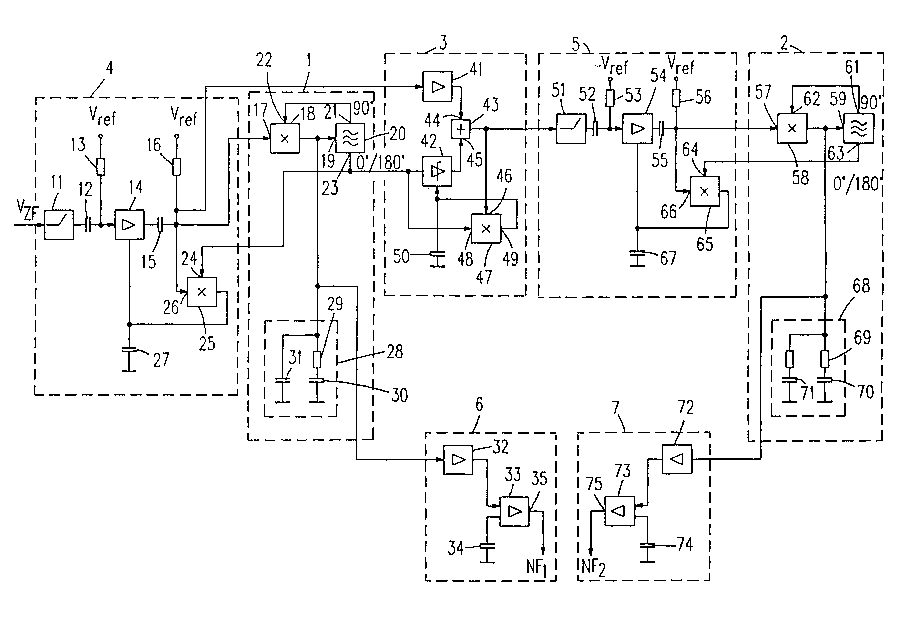
[0010]Moreover, a carrier suppression circuit is provided which superimposes the output signal of the oscillator of the first phase-locked loop, which has locked in at the first sound carrier, with the input signal of the first phase-locked loop in which both sound carriers are present. This is effected by means of an output signal of the oscillator with a 0° or 180° phase shift which is additively or subtractively superimposed on the input signal of the phase-locked loop so that the components of the first sound carrier cancel each other in this signal. It is thereby achieved that the amplitude of the first sound carrier is strongly suppressed in this signal which is applied to the second phase-locked loop. Thus, the second phase-locked loop receives a signal in which the second sound carrier, as compared with the first, is so strong that the phase-locked loop can, in any case, securely lock in on the second sound carrier, even when the first sound carrier is clearly larger than the second sound carrier in the intermediate-frequency signal. Due to the superposition in the carrier suppression circuit and the suppression achieved thereby of the first sound carrier, the second sound carrier is, in any case, stronger than the first sound carrier so that the second phase-locked loop can securely lock in on the second sound carrier.
[0011]It is thereby achieved that, independent of the amplitude ratios of the two sound carriers, the two phase-locked loops can securely lock in on that sound carrier on which they should lock in, and that they do not lock in on the other, possibly stronger sound carrier in the intermediate-frequency signal.
[0012]The circuit arrangement neither requires external ceramic filters nor bandpass filters so that it can be fully integrated. Moreover, it does not require adjustment and has a simple circuitry. A satisfactory suppression of the first sound carrier in the signal applied to the second phase-locked loop is achieved, so that also strongly deviating sound carrier amplitudes do not disturb the demodulation. Moreover, the circuit is suitable for many standards, i.e, the frequencies of the sound carriers may fluctuate within limits so that also different sound carrier frequencies can be processed. This is possible without any additional change or adjustment of the circuit arrangement.
[0021]The implementation of the two phase-locked loops in such a way that they lock in at the frequency of the appropriate sound carrier may be advantageously achieved in that, in accordance with a further embodiment of the invention, the narrow-band phase-locked loops have a digital lock-in means which maintains the frequency of the voltage-controlled oscillator in a predetermined frequency range.

Problems solved by technology

Since such demodulators are usually built into integrated circuits, such bandpass filters interfere because they cannot be realized within the IC but must be realized by means of additional external components which do not only require an additional external number of components, but the IC must also be provided, with equally additional connection, which is also detrimental.

Method used


Image

  • Stereo/two-tone demodulator
  • Stereo/two-tone demodulator

Examples


Embodiment Construction

[0026]The input of the circuit arrangement receives an intermediate-frequency (IF) signal VZF comprising a first and a second sound carrier on which a stereo or a two-tone signal is modulated. These two sound carriers may have strongly deviating amplitudes, with differences that may be 20 dB and more. Dependent on the transmission standard, the amplitude of the first sound carrier having the lower frequency is generally larger than the frequency of the second sound carrier. Picture signal components may also be present in the IF signal. These components may, however, also be filtered out previously by circuit elements which are not shown in the FIGURE.

[0027]In any case, the IF signal VZF comprises the two sound carriers in an intermediate-frequency position.

[0028]The circuit arrangement comprises a first narrow-band phase-locked loop 1 (NBPLL) which is implemented in such a way that it locks in at the frequency of the first sound carrier having the lower frequency, and a second NBPL...


PUM


Abstract

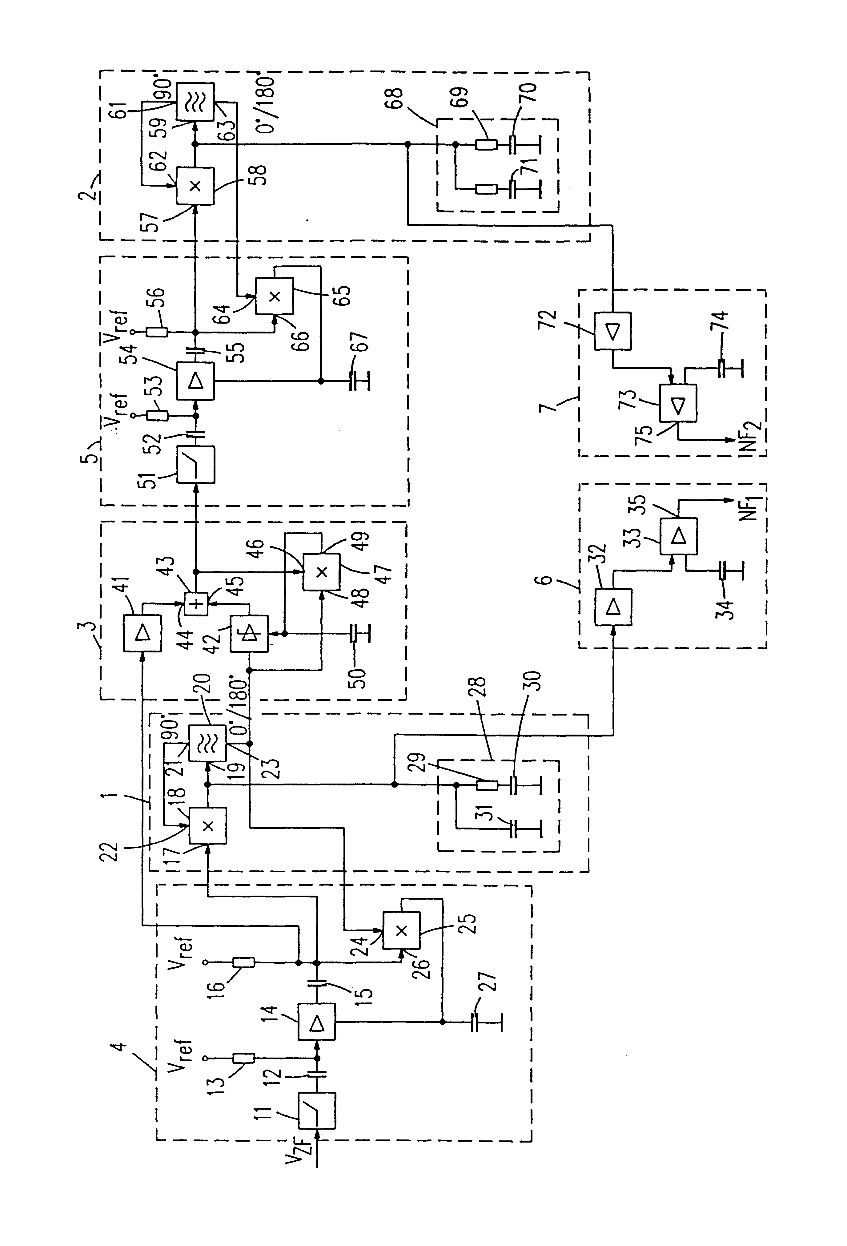
In a stereo / two-tone demodulator for demodulating an intermnediate-frequency signal having stereo or two-tone sound signals modulated on a first and a second sound carrier, the second sound carrier having a lower amplitude than the first sound carrier, ceramic filters or bandpass filters are saved and complete integration can be achieved in that a first (1) and a second (2) linear narrow-band phase-locked loop are provided each having their own frequency selectivity, the first narrow-band phase-locked loop (1) being implemented in such a way that it locks in at the frequency of the first sound carrier, and the second narrow-band phase-locked loop (2) being implemented in such a way that it locks in at the frequency of the second sound carrier. The first narrow-band phase-locked loop (1) is preceded by a first amplifier stage (4) and the second narrow-band phase-locked loop (2) is preceded by a second amplifier stage (5), each amplifier stage controlling the input signal of the subsequent phase-locked loop (1; 2) at a nominal amplitude. A carrier suppression circuit (3) is provided in which an output signal having a phase position of 0° or 180° of a voltage-controlled oscillator (20) of the first narrow-band phase-locked loop (1) and the input signal of the first narrow-band phase-locked loop (1) are superimposed and which supplies a modified interrnediate-frequency signal as an output signal in which the first sound carrier is suppressed and which is coupled to the second amplifier stage (5) preceding the second narrow-band phase-locked loop (2).

Description

BACKGROUND OF THE INVENTION[0001]1. Field of the Invention[0002]The invention relates to a stereo / two-tone demodulator for demodulating an intermediate-frequency signal comprising stereo or two-tone sound signals modulated on a first and a second sound carrier, the second sound carrier having a lower amplitude than the first sound carrier.[0003]2. Description of the Related Art[0004]When a stereo or a two-tone signal is transmitted, an intermediate-frequency signal, which may also comprise a picture signal, has two sound carriers on which ,sound signal components are modulated. Dependent on the transmission standard, the two sound carriers do not have equal amplitudes. One of the sound carriers may be up to 20 dB smaller as compared with the other.[0005]In known stereo / two-tone demodulators, either ceramic bandpass filters preceding the demodulator are used, or bandpass filters are arranged within the demodulator. Since such demodulators are usually built into integrated circuits, s...

Claims


Application Information

Patent Timeline
IPC IPC(8): H04H5/00H04B1/26H03D1/22H03D3/24H04B1/16H04H20/88H04N5/60H04S1/00
CPCH03D1/2236H04S1/00H04N5/607
Inventor BRILKA, JOACHIM
Owner KONINKLIJKE PHILIPS ELECTRONICS NV
Learn More