
High voltage surge protection element for use with CATV coaxial cable connectors

a technology of high-voltage surge protection and catv, which is applied in the direction of overvoltage protection resistors, emergency protective arrangements for limiting excess voltage/current, and arrangements responsive to excess voltage, etc., can solve problems such as devices becoming inoperable, and achieve the effect of convenient installation and inexpensive manufactur

Inactive Publication Date: 2006-09-05
JOHN MEZZALINGUA ASSOC INC
View PDF4 Cites 119 Cited by
  • Summary
  • Abstract
  • Description
  • Claims
  • Application Information

AI Technical Summary

Benefits of technology

[0007]It is therefore a principal object and advantage of the present invention to provide a cable connector having a device that provides an alternate path for high voltage surges of electricity in order to protect the integrity of any electrical components positioned within the connector.
[0008]It is an additional object and advantage of the present invention to provide a surge protection device that may be easily installed on an otherwise conventional cable connector.
[0009]It is a further object and advantage of the present invention to provide a surge protection device for a cable connector that is inexpensive to manufacture.
[0010]Other objects and advantages of the present invention will in part be obvious, and in part appear hereinafter.SUMMARY OF THE INVENTION
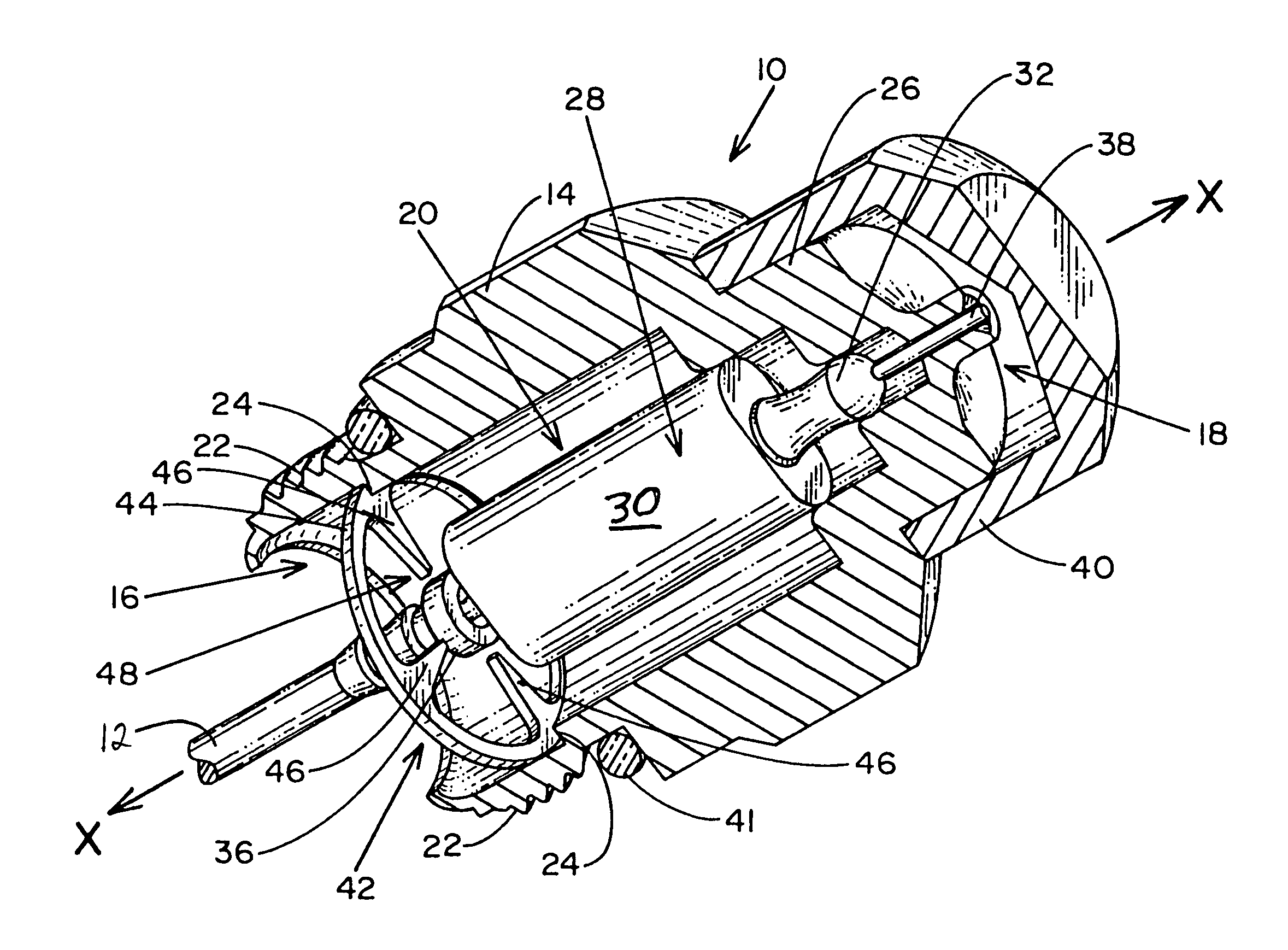
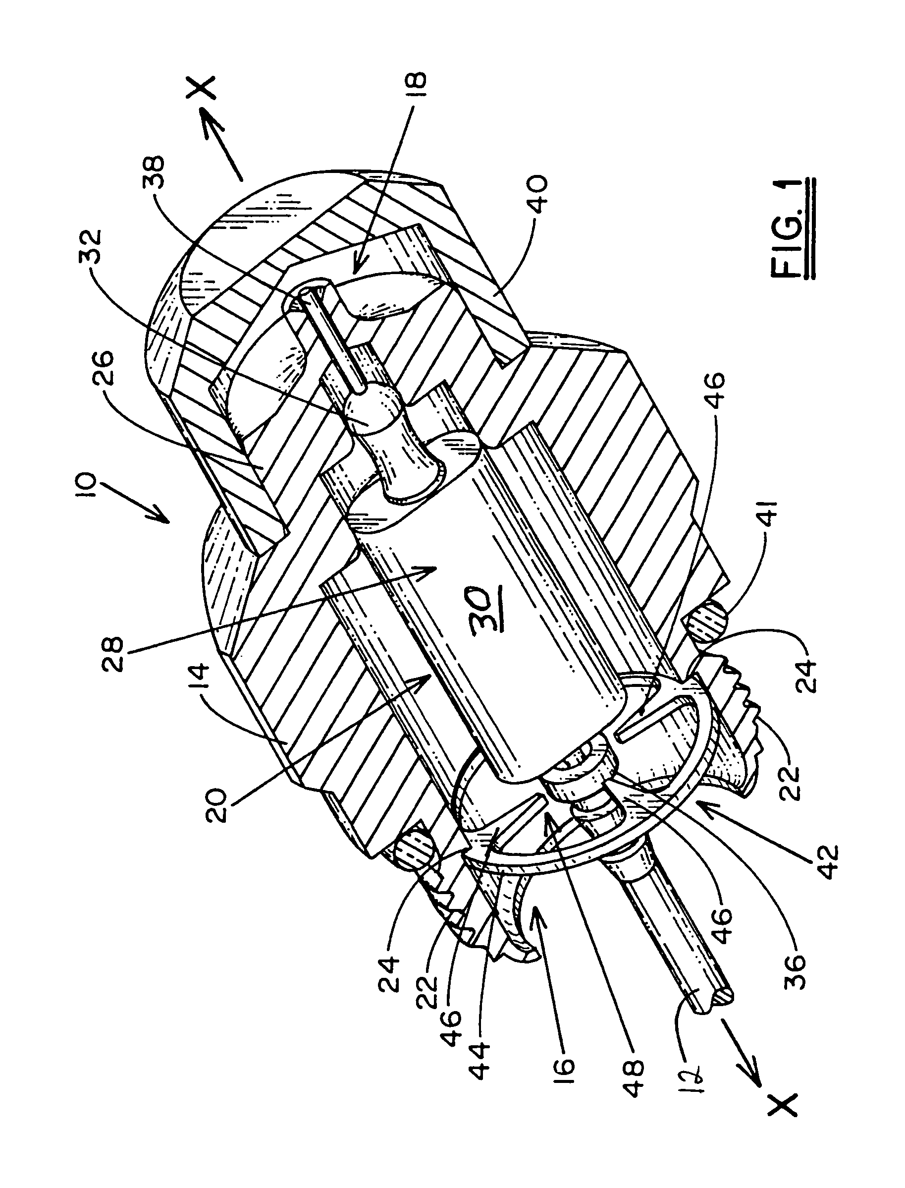
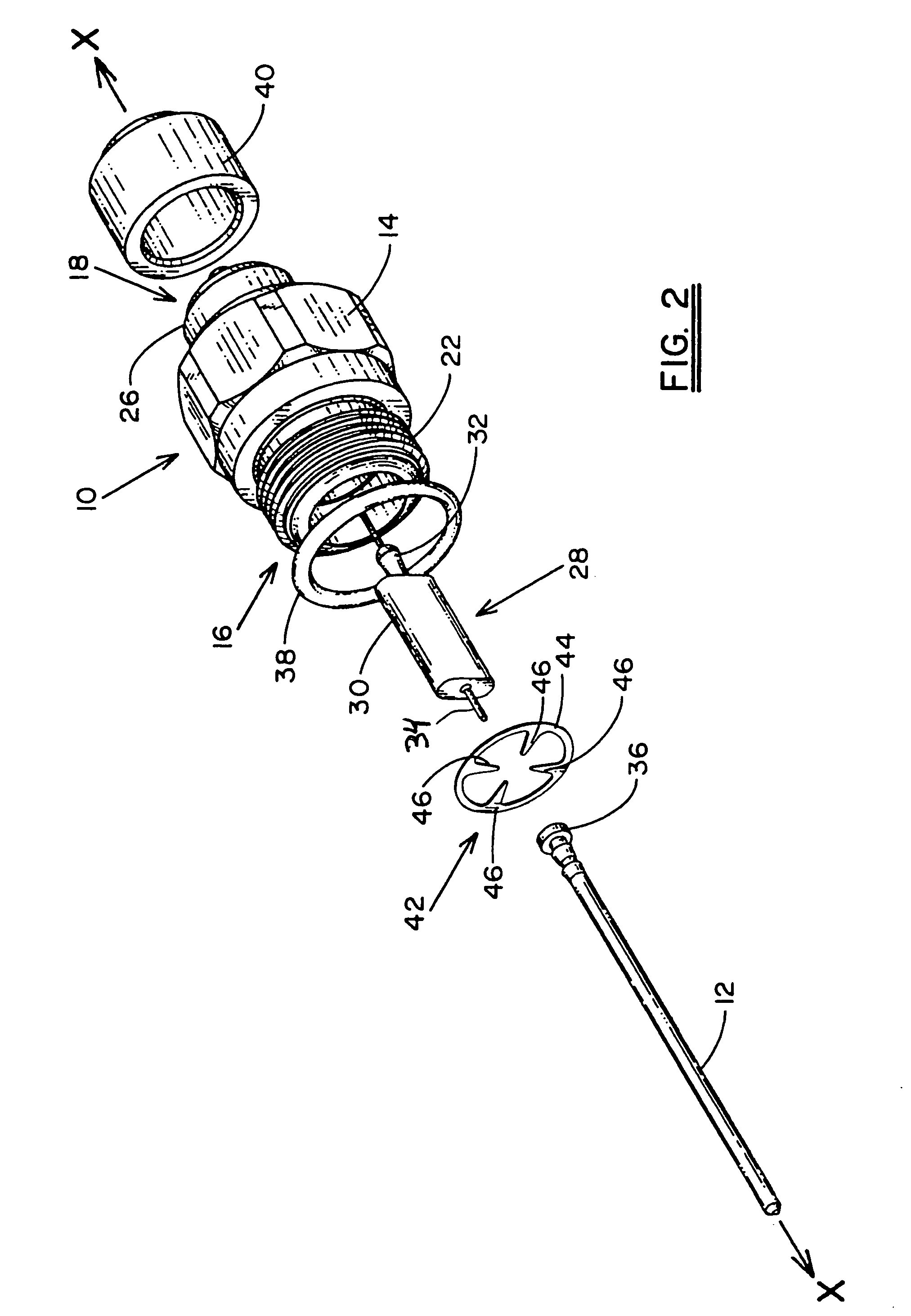
[0011]In accordance with the forgoing objects and advantages, the present invention provides a conventional cable connector, such as a UMTR (Universal Male Terminator type connector), that further comprises an element for protecting the electrical components positioned within the connector from high voltage surges. The surge protection element comprises a ring that is positioned in circumferentially surrounding relation to the input pin that carries the signal being transmitted by the coaxial cable. The ring includes at least one, and preferably three prongs that extend radially inwardly therefrom and terminate in close, but non-contacting relation to the pin.
[0012]The ring portion of the surge protection element is positioned in contacting relation to a shoulder formed on the body of the cable connector, and is composed of an electrically conductive material, such as, but not limited to, brass. The coaxial cable, which is electrically interconnected to the head of the pin (it should be understood that there may be other common elements disposed between the coaxial cable and head of the pin, such as a tap), passes through the ring portion, adjacent the prong(s), but in non-contacting relation thereto, thereby forming a gap between the prong(s) and cable. If a high voltage surge of electricity is carried by the coaxial cable, such as might occur if it is struck by lightening, a spark will be formed in the gap between the prongs and the cable due to the conductive composition of the surge protection element. As a consequence, the high voltage surge will be transferred to the surge protection element which, in turn, will conduct the electricity to the body of the connector to which it is positioned in contacting relation. The body of the conductor will then carry the high voltage surge of electricity around the electrical components positioned within it, and ultimately to ground. Thus, the high voltage surge will not pass into the electrical components positioned within the connector.

Problems solved by technology

If this high voltage surge is permitted to be picked up by the input pin and transmitted to the electrical device within the connector, the device would become inoperable due to the electrical components essentially melting or otherwise deteriorating as a consequence of the surge.

Method used


Image

  • High voltage surge protection element for use with CATV coaxial cable connectors
  • High voltage surge protection element for use with CATV coaxial cable connectors
  • High voltage surge protection element for use with CATV coaxial cable connectors

Examples


Embodiment Construction

[0022]Referring now to the drawings, wherein like reference numerals refer to like parts throughout, there is seen in FIG. 1 a coaxial cable connector, designated generally by reference numeral 10, extending along a longitudinal axis X—X and having a coaxial cable interconnected thereto. Although not expressly illustrated in the drawings, it should be understood that the coaxial cable comprises a central conductor immediately surrounded by a layer of dielectric material of predetermined thickness, an outer conductor concentric with the central conductor and surrounding the dielectric material, and an outer layer of insulating material surrounding the exterior surface of the outer conductor.

[0023]Connector 10 generally comprises a conductive body 14 having an input end 16, an output end 18, and a cavity 20 defined therein. Body 14 includes an externally threaded portion 22 positioned at its input end 16 (it should be understood that connector 10 is illustrated as being a “male” UMTR ...


PUM


Abstract

An electrically conductive element for protecting electrical components positioned within a cable connector or cable terminator from high voltage surges includes a ring that is positioned in circumferentially surrounding relation to the input pin of the connector or terminator that carries the signal being transmitted by the coaxial cable. The ring includes at least one prong that extends radially inward therefrom which terminates in close but non-contacting relation to the input pin. When a high voltage surge of electricity is carried by the coaxial cable transmission line, a spark is formed in the gap between the prong and the cable connector or terminator. As a consequence, the high voltage surge is transferred to the surge protection element which in turn conducts the electricity to the grounded body of the connector or terminator.

Description

CROSS-REFERENCE TO RELATED APPLICATIONS[0001]This application is a continuation of and claims priority from U.S. patent application Ser. No. 09 / 726,821 filed Nov. 30, 2000 now U.S. Pat. No. 6,683,773 and entitled HIGH VOLTAGE SURGE PROTECTION ELEMENT FOR USE WITH CATV COAXIAL CABLE CONNECTORS.BACKGROUND OF THE INVENTION[0002]The present invention relates generally to devices for interconnecting coaxial cable to CATV systems, and more particularly to surge protection devices that protect the integrity of electronic components positioned within interconnect devices from high voltage surges of electricity.[0003]In the CATV industry, cable television signals are traditionally transmitted by coaxial cable. As the cable is extended through a distribution network, several types of electrical devices, such as filters, traps, amplifiers, and the like, are used to enhance the signal and ensure signal integrity throughout the transmission. It is therefore necessary to prepare a coaxial cable f...

Claims


Application Information

Patent Timeline
IPC IPC(8): H02H1/00H01T4/08
CPCH01T4/08
Inventor MONTENA, NOAH
Owner JOHN MEZZALINGUA ASSOC INC
Learn More