Planetary-gear-type multiple-step transmission for vehicle

a transmission and planetary gear technology, applied in mechanical equipment, gearing, transportation and packaging, etc., can solve the problems of increasing the overall length of the transmission, reducing the degree of freedom in the installation of the transmission on the vehicle, and poor maneuverability of the transmission, etc., and achieve the effect of small axial length

Inactive Publication Date: 2006-09-05
TOYOTA JIDOSHA KK
View PDF18 Cites 313 Cited by
  • Summary
  • Abstract
  • Description
  • Claims
  • Application Information

AI Technical Summary

Benefits of technology

[0038]Each of the above-described seventh and eighteen aspects of the invention provides the planetary-gear-type multiple-step transmission which can be constituted by a further reduced number of components and which can have a further reduced axial length.
[0042]For example, in the planetary-gear-type multiple-step transmission of each of the above-described first through twelfth and fifteenth through twenty-third aspects of the invention, the first transmission unit may have two pairs of power transmitting members which are arranged in parallel with each other, wherein one of the two pairs of the power transmitting members is connected to the input rotary member and the first intermediate transmitting path while the other of the two pairs of the power transmitting members is connected to the input rotary member and the second intermediate transmitting path. The two pairs of power transmitting members may be provided by first and second pairs of counter gears consisting of first drive and driven gears and second drive and driven gears, like counter gears of a parallel-axes-type transmission, such that the first and second drive gears are mounted on a first shaft to which the input rotary member is connected while the first and second driven gears are mounted on a second shaft which is parallel with the first shaft and which corresponds to a common axis of the three planetary gear sets of the second transmission unit. Where the reduction gear ratio of the second pair of counter gears is made larger than that of the first pair of counter gears, the first transmission unit transmits the rotary motion from the input rotary member to the second transmission unit such that the speed of the rotary motion as transmitted through the second intermediate transmitting path is lower than the speed of the rotary motion as transmitted through the first intermediate transmitting path. This arrangement, in which the first transmission unit have the two pairs of power transmitting members in place of the planetary gear set, permits the transmission to have relatively width range of speed ratio and appropriate ratio steps between adjacent drive positions, as the arrangement in which the first transmission unit have the planetary gear set. Further, this arrangement is advantageous over a transmission having four planetary gear sets arranged in series on a single axis, in that its relatively small axial length permits the transmission to be advantageously used for a front-engine front-drive (FF vehicle) or a rear-engine rear-drive (RR vehicle) on which a transmission is preferably installed with an axis of the transmission being parallel to the transverse or lateral direction of the vehicle.

Problems solved by technology

In the multiple-step transmission disclosed in JP-2002-206601A, however, the speed ratios of the respective operating positions do not change in geometric progression, thereby resulting in a poor maneuverability in the transmission.
However, the increase in the number of planetary gear sets leads to an increase in an overall length of the transmission, thereby possibly reducing a degree of freedom in installation of the transmission on a vehicle, while increasing number of coupling devices required for connecting elements of the planetary gear sets.

Method used


Image

  • Planetary-gear-type multiple-step transmission for vehicle
  • Planetary-gear-type multiple-step transmission for vehicle
  • Planetary-gear-type multiple-step transmission for vehicle

Examples


first embodiment

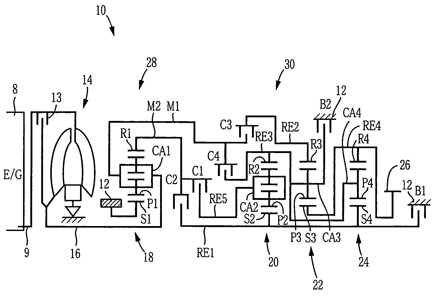
[0109]Referring to first to the schematic view of FIG. 1, there is illustrated a basic arrangement of a vehicle automatic transmission in the form of a vehicle planetary gear type multiple-step transmission (hereinafter referred to simply as “transmission”) 10, which is to be disposed between an engine 8 as a drive power source and drive wheels (not shown) so as to transmit an output of the engine 8 to the drive wheels. As shown in FIG. 1, the transmission 10 has a transmission casing 12 to be fixed to the body of the vehicle, and includes: a hydraulic transmission unit in the form of a torque converter 14 equipped with a lock-up clutch 13; an input shaft 16 connected to the torque converter 14; a first transmission unit 28 constituted principally by a first planetary gear set 18; a second transmission unit 30 constituted principally by a second planetary gear set 20, a third planetary gear set 22 and a fourth planetary gear set 24; and an output gear 26. The torque converter 14, th...

second embodiment

[0136]In this second embodiment, the second planetary gear set 20 of the second transmitting unit 30 is of double-pinion type, while the third and fourth planetary gear sets 22, 24 are of single-pinion type. The second planetary gear set 20 includes a second sun gear S2, plural pairs of second planetary gears P2 (each pair of gears P2 mesh with each other), a second carrier CA2 supporting the second planetary gears P2 (such that the second planetary gears P2 are rotatable about their respective axes and are rotatable about the axis of the second sun gear S2), and a second ring gear R2 meshing with the second sun gear S2 through the second planetary gears P2. The second planetary gear set 20 has a predetermined gear ratio ρ2, for instance, about 0.468. The third planetary gear set 22 includes a third sun gear S3, a plurality of third planetary gears P3, a third carrier. CA3 supporting the third planetary gears P3 (such that the third planetary gears P3 are rotatable about their respe...

third embodiment

[0142]In this third embodiment, the second and fourth planetary gear sets 20, 24 are of single-pinion type, while the third planetary gear set 22 is of double-pinion type. The third planetary gear set 22 includes a third sun gear S3, plural pairs of third planetary gears P3 (each pair of gears P3 mesh with each other), a third carrier CA3 supporting the third planetary gears P3 (such that the third planetary gears P3 are rotatable about their respective axes and are rotatable about the axis of the third sun gear S3), and a third ring gear R3 meshing with the third sun gear S3 through the third planetary gears P3. The third planetary gear set 22 has a predetermined gear ratio ρ3, for instance, about 0.368. The second planetary gear set 20 includes a second sun gear S2 provided by a common sun gear which provides also the third sun gear S3, a plurality of second planetary gears P2 each provided by a common planetary gear which provides also one of the corresponding pair of third plane...


PUM


Abstract

A planetary-gear-type multiple-step transmission including a stationary member, an input rotary member, an output rotary member, and first and second transmission units. The first transmission unit transmits a rotary motion from an input rotary member to the second transmission unit through first and second intermediate transmitting paths such that a speed of the rotary motion transmitted through the second intermediate transmitting path is lower than that of the rotary motion transmitted through the first intermediate transmitting path. The second transmission unit constitutes first, second, third, fourth and fifth rotary elements, each of which is provided by at least one of sun gears, carriers and ring gears of three planetary gear sets. The first rotary element is selectively connected to the second intermediate transmitting path, while being selectively connected to the stationary member. The second rotary element is selectively connected to the first intermediate transmitting path. The third rotary element is selectively connected to the first intermediate transmitting path, while being selectively connected to the stationary member. The fourth rotary element is connected to the output rotary member. The fifth rotary element is selectively connected to the second intermediate transmitting path.

Description

[0001]This application is based on Japanese Patent Applications No. 2003-149926 filed in May 27, 2003 and No. 2003-289464 filed in Aug. 7, 2003, the contents of which are incorporated hereinto by reference.BACKGROUND OF THE INVENTION[0002]1. Field of the Invention[0003]The present invention relates to a planetary-gear-type multiple-step transmission interposed between a drive power source and drive wheels of a vehicle such as an automobile.[0004]2. Discussion of Related Art[0005]For vehicle, there is widely used a planetary-gear-type multiple-step transmission which is equipped with a plurality of planetary gear sets, as disclosed in JP-2002-206601A, JP-H08-105496A, JP-2000-199549A, JP-2000-266138A, JP-2001-82555A, JP-2002-227940A, JP-2002-295609A and JP-2956173B2. In such a planetary-gear-type multiple-step transmission, a plurality of predetermined speed ratios or operating positions (gear positions) are selectively established by connecting elements of the planetary gear sets thr...

Claims


Application Information

Patent Timeline
IPC IPC(8): F16H3/62F16H3/44F16H3/66F16H37/04
CPCF16H3/663F16H3/666F16H37/04F16H2200/0056F16H2200/2097F16H2200/2007F16H2200/201F16H2200/2012F16H2200/2023F16H2200/006
Inventor TABATA, ATSUSHIHOSHINO, AKIRAMIYAZAKI, TERUFUMIHONDA, ATSUSHIABE, AKIHARUOTA, HIROFUMI
Owner TOYOTA JIDOSHA KK
Why Eureka
Try Eureka